
Figure 3.
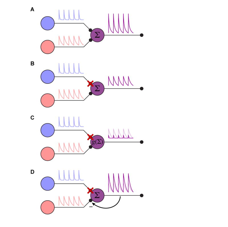
Circuit manipulation. (A) Cartoon of a simple, intact circuit. The purple cell simply sums the synaptic input from the red and blue cells. (B) Illustration of a simply interpretable silencing outcome. When the blue cell is silenced, the purple cell now simply reports the red cell’s activity. The entire system is linear in this case. (C) Illustration of dynamic range confounding interpretation. In this case, when the blue cell is silenced, the lack of a tonic blue input moves the purple cell below its natural dynamic range, clipping the remaining input. This is the equivalent of putting a nonlinearity g(.) on the summation of the inputs. The linear case is shown in light purple for comparison. (D) Illustration of feedback gain confounding interpretation. In this case, the inputs are summed, but the purple cell provides negative feedback on the gain from the red and blue cells. When the blue cell is silenced, the gain on the red synapse is increased to accommodate the lesser total input. The linear case is shown in light purple for comparison. Cases (C) and (D) illustrate complications to interpreting silencing experiments in even very simple circuits; similar caveats will apply to activation experiments.