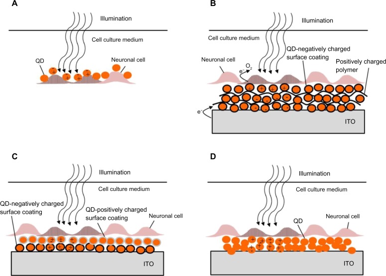
Figure 3.
Quantum dots for neuronal photoactivation.
Notes: (A) Direct wiring of QDs to neuronal cell membrane according to the scheme studied by Winter et al (2001).147 Illumination results in charge separation in the QDs, electric field buildup and cell activation. (B) QD coated device according to the scheme reported by Pappas et al (2007).149 A QD film is composed of layers of QDs and a polymer. Upon illumination the photogenerated electrons are transferred to oxygen in the solution. This results in accumulation of holes. The photocurrent, activating the neuronal cells originates from the electrons injected from the ITO surface in response to the accumulation of holes. (C) A QD film composed of layers of QDs with opposite-polarity surface coating according to the scheme presented by Lugo et al (2012).150 (D) An alternative route to QD film deposition, also studied by Lugo et al (2012),150 prepared by drop coating. This approach was also used for coating of a glass micropipette probe. In both (C and D), light generated dipoles in the QD layer are associated with an electric fields designed to activate neurons when placed close enough to the cells.
Abbreviations: ITO, indium tin oxide; QD, quantum dot.

