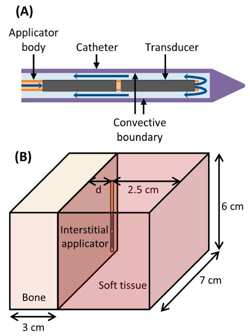
Figure 1.
(A) Diagram of the ultrasound applicators modeled. Blue arrows indicate the direction of cooling flow, which runs through the center of the applicator, out the tip, and then between the applicator and the catheter. Transducers have an outer diameter of 1.5 mm. The catheter has an outer diameter of 2.4 mm and an inner diameter of 1.89 mm. A convective boundary condition is applied to the inner wall of the catheter. (B) Geometry used to model interstitial ultrasound ablation with the applicator at various distances (0.5 cm < d < 3.2 cm) from the surface of a flat bone.

