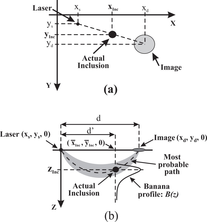
Fig. 6.
Illustration of the approach used to locate the inclusion in 3D. a) Illustrates the principle for finding the in plane location of the inclusion for the illumination point at coordinates (xs, ys). This produces at (xd, yd) a blurred image of the inclusion, which is actually located at (xInc, yInc). b) Shows how to retrieve the depth of the inclusion once the average values of the in plane coordinates, (x̄Inc, ȳInc), are known. The plane of this Figure is the one defined by the z axis and the line joining the illumination point and the image. See text for a detailed explanation.

