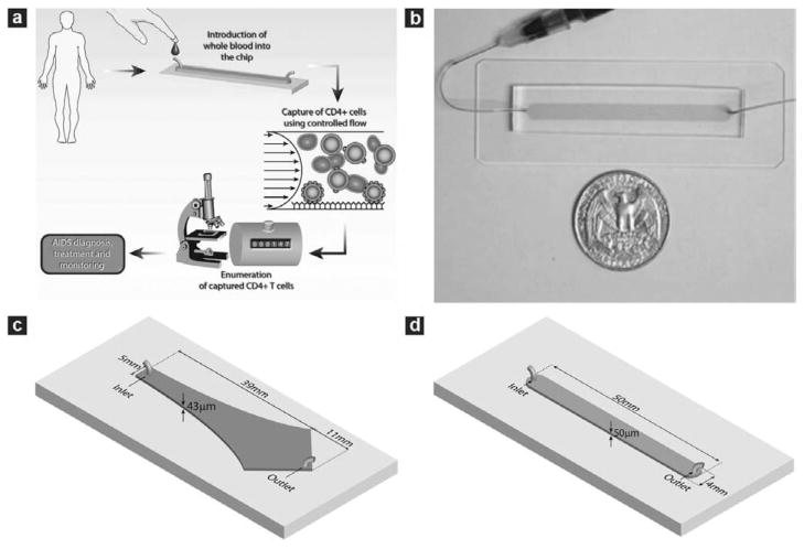
Fig. 1.
Microfluidic devices used in the study and operating procedure of the counting device. (a) Schematic depiction showing the operating procedure of the CD4 counting device. The microchip is operated by injecting 10 μL whole blood at controlled flow rate. This is followed with rinsing unbound cells from the chamber and counting all the captured cells within the chip using an optical microscope to obtain CD4 counts. (b) Photograph of a linear cell count device. Microfabricated PDMS devices with one inlet and one outlet were bound to glass slides to form closed chambers. The chamber was functionalized with specific antibody to capture target cells from whole blood. The shaded area indicates the chamber location within PDMS. (c) Geometry of the Hele–Shaw device. The Hele–Shaw device offers a linear variation of shear along its central line. It was used in this study to screen the optimal shear stress for cell capture. (d) Geometry of the linear cell count device. The linear device has a volume of 10 μL for sample volume metering. It was operated under the optimized shear stress to capture and numerate the target cells.

