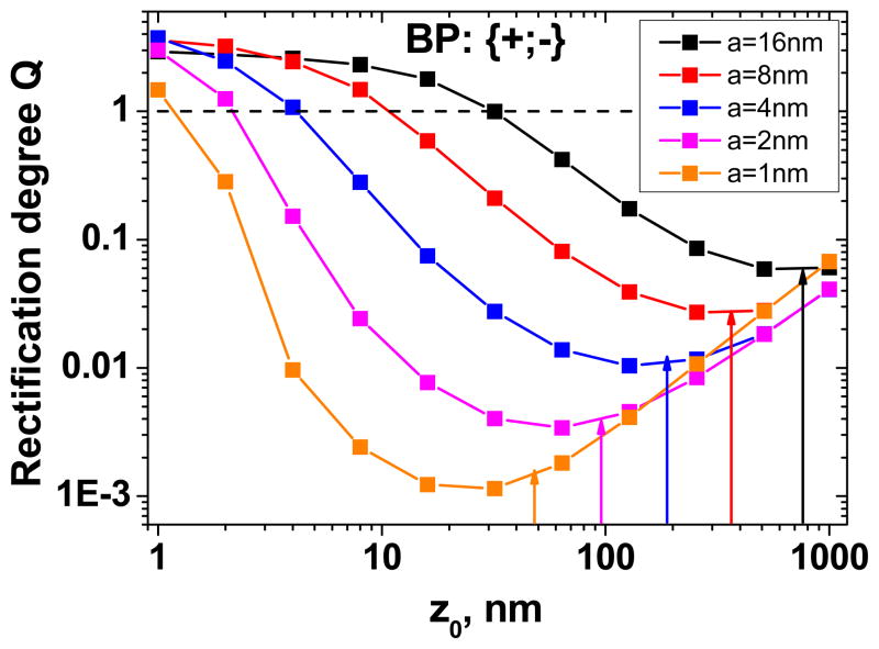
Figure 4.
Numerically calculated rectification degrees of bipolar (BP) diodes based on single conically shaped pores, as a function of the transition zone location (z0), and the tip radius (a). Only one configuration {+;−} is shown since the rectification degree of the device {−;+} can be calculated as the reverse of the shown values. The arrows indicate the position of the transition zone that assures the highest rectification degree, as estimated by Eq. 4. The calculations were performed for L = 12μm, A = 250nm, Cbulk = 0.1M and σ= −0.5e/nm2.

