
Figure 2.
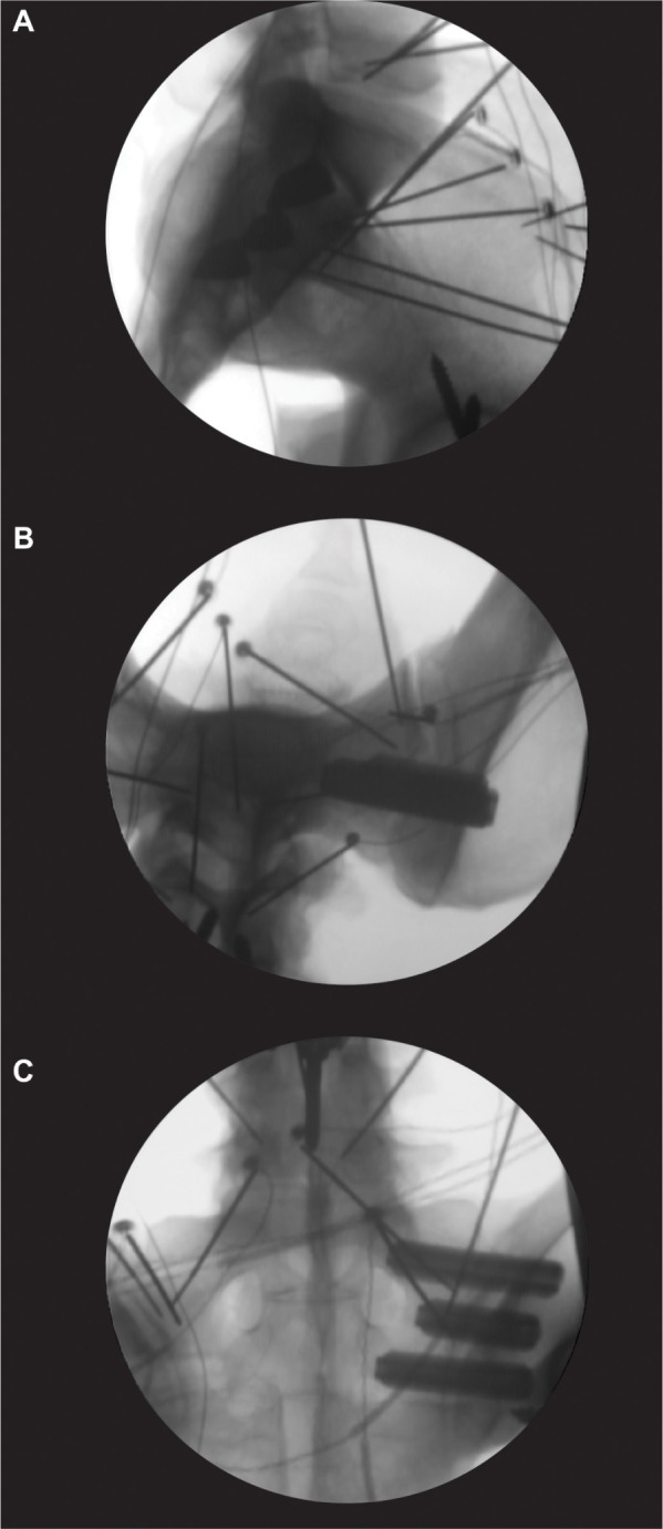
Representative fluoroscopic images showing placement of the three 7.0 mm implants placed in the (A) lateral, (B) inlet, and (C) outlet views.
Note: The wires and pins supporting the infrared LED markers for the tracking system are visible in the radiographs.
Abbreviation: LED, light-emitting diode.