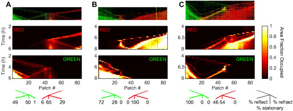
Figure 3.

Decomposition of colliding colonization waves. The top row shows kymographs of fluorescence intensity, the second row shows occupancy levels for strain JEK1037 (red), the third row the occupancy levels for strain JEK1036 (green), and the bottom row the post-collision distributions of bacteria over the reflected, stationary and refracted components (from left to right for green and from right to left for red), as determined from the occupancy distribution 1 hour after the collision. Examples where: (A) Both waves have large reflected parts. (B) Red wave forms a stationary population. (C) Most of the red wave is refracted. Also note how a combined wave (yellow, in top row) is formed when the red β wave collides with a stationary green population (t = 6.5 h, patch 50).
