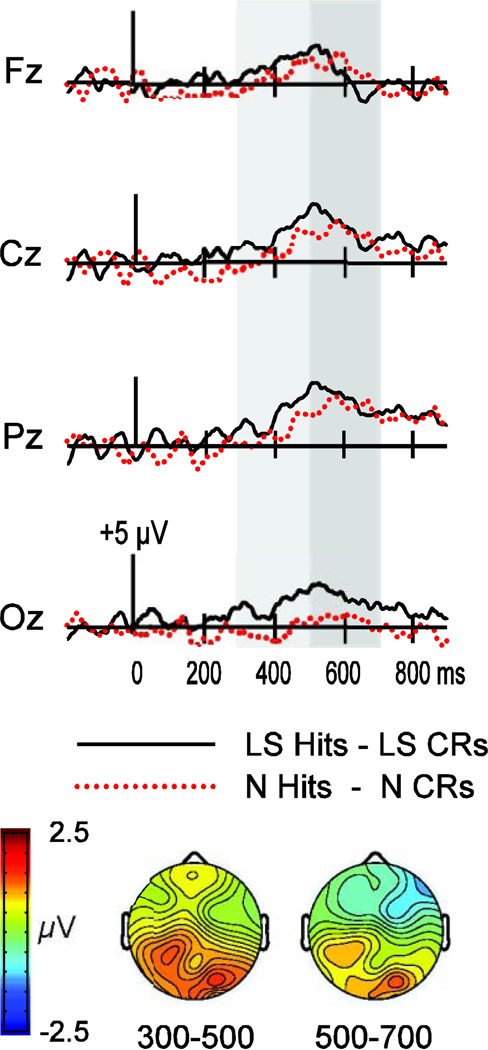
Figure 2.
Waveforms depicting the subtraction between hits and correct rejections (CRs) in the N and LS conditions in Experiment 1 (N condition, dotted red trace; LS condition, solid black trace). Waveforms are shown for four midline electrodes (Fz, Cz, Pz, Oz). Gray shading indicates the time intervals of interest (300–500 ms and 500–700 ms). Topographic maps depict the hit/CR effect in the LS condition minus that in the N condition over each time interval.

