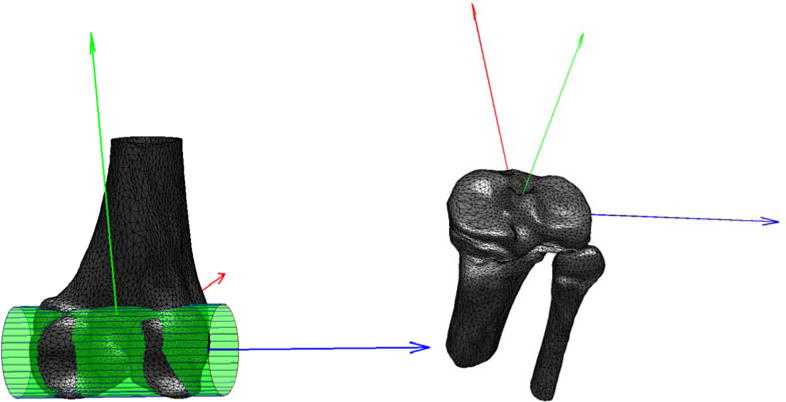
Figure 3.

Femoral and tibial coordinate systems. A cylinder fitted to the posterior condyles determined the ML femoral axis (blue), whose mid-point served as origin. The AP axis (red) was defined perpendicular to the ML axis and the femoral shaft. The proximal-distal (PD) axis (green) was set orthogonal to the AP and ML directions. For the tibial coordinate-system, the tibial plateau was identified as the plane with the largest surface area orthogonal to the tibial shaft. The plateau's center of mass was used as origin, and its inertial axes as the ML (blue) and AP (red) axes.
