Figure 2.
Design of an array of microwells for microengraving.
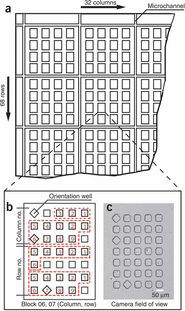
(a) Schematic representation of the top-left corner of the array showing a network of microchannels and 4 × 4 groups of blocks containing microwells. (b) Annotated illustration of one block comprising a 5 × 7 arrangement of microwells. Each well projects a square cross-section and has a cuboid geometry in the molded array. Certain wells are rotated 45° within a given block to encode the precise position of that block within the array of blocks (e.g., 32 × 68). The rotated well in the top-left corner of a block establishes the orientation of the array and is present in the same position in every block. The presence or absence of rotated wells in other areas of the block encodes the location (row and column) of the block within the entire array. Here, the areas outlined with red, dashed lines indicate the block column and row numbers as two-digit integers (columns 01–32, rows 01–68). In the area labeled on the scheme for encoding the column, the topmost region (bound by red, dashed lines) is used to indicate the first digit of the column number, whereas the region immediately below indicates the second digit of column number. The same scheme is applied in the lower region of the block to encode the row. The position of a rotated well within these designated areas specifies the first or second digit of the column or row number; zero is indicated by the absence of a rotated well. In the example shown here, the positions of the rotated wells, read from top to bottom, indicate Block 06, 07 (column, row). (c) Transmitted-light micrograph of Block 06, 07 loaded with hybridoma cells (HYB9901) acquired at a magnification of ×10 with a Hamamatsu ORCA-AG digital camera. The entire field of view of the camera is shown. Scale bar, 50 µm.

