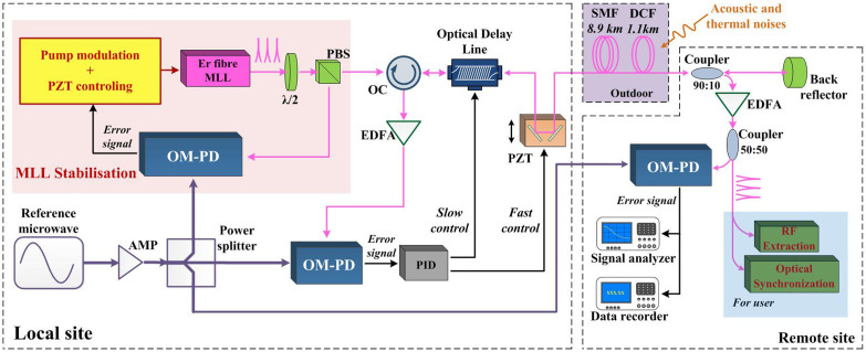
Figure 2. Experimental setup for the optical-pulse-train distribution and measurement system.
A stabilised optical pulse train is distributed to a “remote site” via a 10-km fibre link. At the remote site, a portion of the pulse train is designated for the user. The rest is reflected back to the “local site” via the same fibre link. An optical-microwave phase-detection technique is used to generate a high-precision phase-error signal to compensate for the phase fluctuations in the fibre link.

