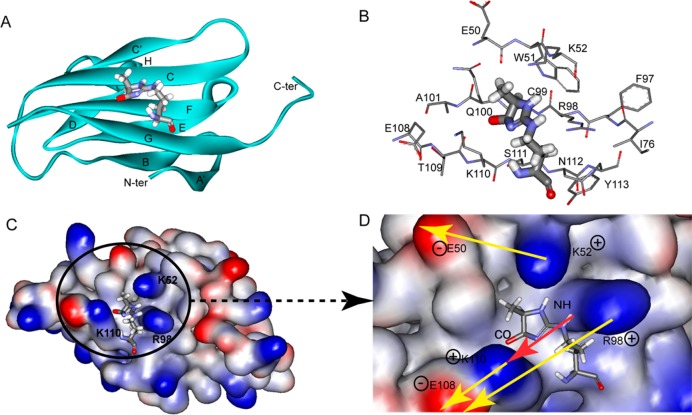
Figure 5.
Solution structure of the MG-H1–V domain complex. (A) Structure of MG-H1 (balls and sticks) bound to the V domain (ribbon representation). Secondary structural elements are labeled following the immunoglobulin convention.47,48 (B) Residues surrounding the interaction surface between MG-H1 and the V domain. (C and D) Electrostatic potential surface of the V domain (C) and a close-up showing dipole–dipole forces (D). MG-H1 fits well into a groove composed of K52, R98, Q100, and K110 on the V domain. Positively and negatively charged surfaces are colored blue and red, respectively. The red arrow represents a dipole of the MG-H1 molecule, and yellow arrows represent environmental dipoles on the V domain surface. Both shape complementarity and dipole–dipole forces contribute to the stabilization of the MG-H1–V domain complex.40,49

