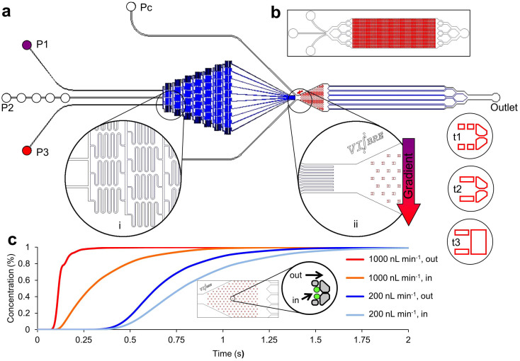
Figure 1. Physical and hydrodynamic features of the microfluidic multitrap nanophysiometer (MTNP).
(a) Schematic showing typical MTNP setup. Pumps supply fluid to the device from left to right through input ports P1–P3. The Pc ports are used for cell loading and to rapidly introduce solutions to the entire array by bypassing the gradient mixer. An optional gradient mixer (i) combines fluids in 10 discrete volumetric ratios before directing them to the trap chamber (ii). Several trap styles (t1–t3) and alternate whole device configurations (b) are easily implemented to accommodate diverse cell types and tissue quantities. (c) COMSOL Multiphysics simulation of time taken for perfusate concentration to reach 100% in the center of the trapping area relative to the trap chamber entrance. Each curve represents the space either directly outside and adjacent to the trap, shown in the inset by the “out” arrow, or within the walls of the trap with two cells present, shown by the “in” arrow, at a flow rate of either 200 nL min−1 or 1000 nL min−1.

