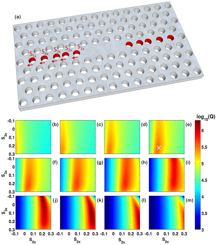
Figure 1.
(a): The design of the L3 cavity. For quality factor optimization, shifts of the positions of the five neighbouring holes in the x-direction were introduced, labeled as S1x, S2x, S3x, S4x, and S5x in the figure. (b)–(m): A parameter scan of the GME-computed quality factor values for different S1x, S2x and S3x, where S1x starts from 0.15a in panel (b) and increases in multiples of 0.02a in every consecutive panel, up to 0.37a in (m), and S4x = S5x = 0 in all panels.

