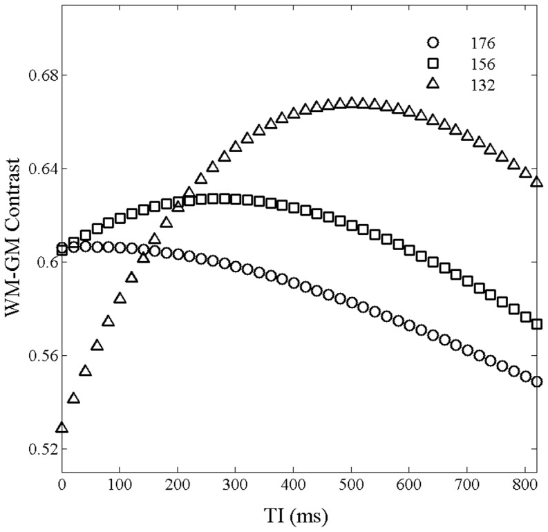
Figure 2. Simulated contrast between the GM and WM as functions of TI for total number of readout RF pulses of 176, 156, and 132.

The interval time between readout RF pulses was set to 10.1; the flip angle was set to 12°.

The interval time between readout RF pulses was set to 10.1; the flip angle was set to 12°.