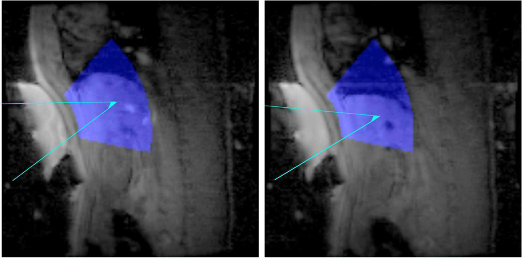
Figure 2. Transducer Tracking.
The tracking coil information, besides determining the location of the transducer coil elements, was also used to visualize potential treatment areas on top of collected scout scans. The areas depicted in blue superimposed on collected scout images show regions that are 5–15 cm from the transducer face, up to an angle of 30 degrees off-axis. The aqua lines depict a target steering path to a focus in the liver from the transducer at two locations of the respiratory cycle.

