Figure 2.
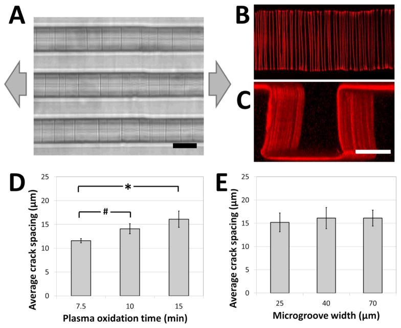
Crack structures fabricated on three-dimensional surfaces. (A) Representative bright-field image of cracks generated in topologically complex PDMS substrates (scale bar = 20 μm; arrows represent direction of applied strain). (B, C) Fluorescent visualization of candidate matrix proteins (TRITC-BSA) adsorbed to crack structures in (B) the bottom of the microgroove (top view), and (C) across the surfaces of the microgroove (perspective view; scale bars = 30 μm). These images and the supplemental movies 1A and B demonstrate that cracks are continuous across the microgroove structure. (D) The crack spacing depends on plasma oxidation treatment times (# p < 0.05, * p < 0.01 by one-tailed t-test). (E) The crack spacing is relatively robust to changes in microgroove widths (no significant differences, p > 0.8). The applied strain in (D) and (E) was 5%.

