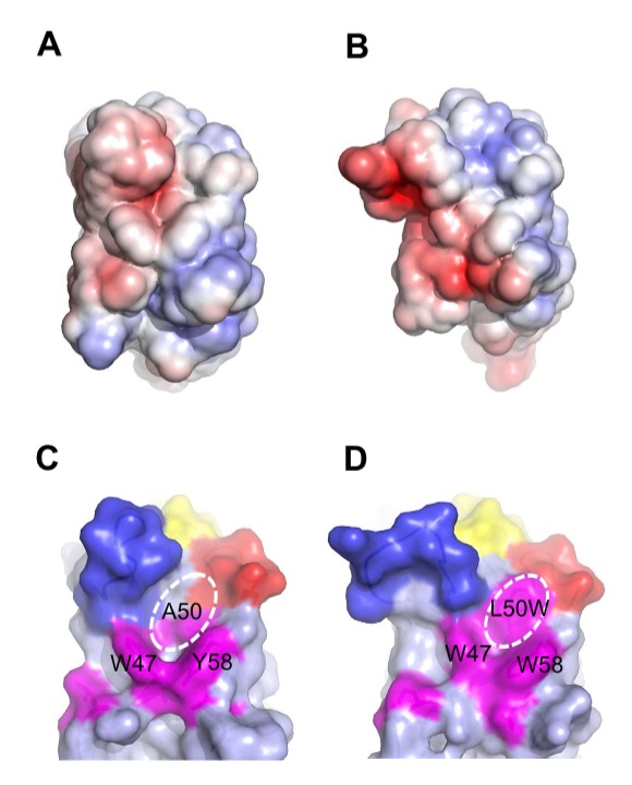
Figure 9. Surface features of MG2x1, MG8-14, and modified MG8-14 [L50W].

(A) Electrostatic charge distribution on the solvent-accessible surface of MG2x1 (red, −5 k; blue, +5 k). (B) Electrostatic charge distribution on the solvent-accessible surface of MG8-14. (C) Surface representation of MG2x1 showing the prominent cavity around residues 50 and 58. CDR regions are colored in yellow (CDRH1), red (CDRH2), and blue (CDRH3). Mutation sites are colored in magenta to highlight the cavity. (D) Surface representation of the structural model of the modified MG8-14 [L50W], in which L50 is replaced by W.
