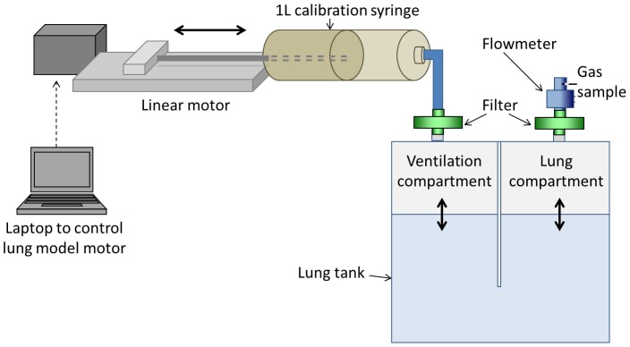
Figure 2. Diagram of lung model.

A high-precision computer-controlled linear motor was used to drive a calibration syringe. This moved air into and out of the ventilation compartment of the lung tank. Water level in the lung compartment determined functional residual capacity (FRC) of the model whilst ventilation rate and volume were controlled by speed and excursion of the linear motor. A flowmeter and gas sample needle were connected to the lung compartment. During washin, a T-piece connected the flowmeter to the open circuit 0.2% SF6.
