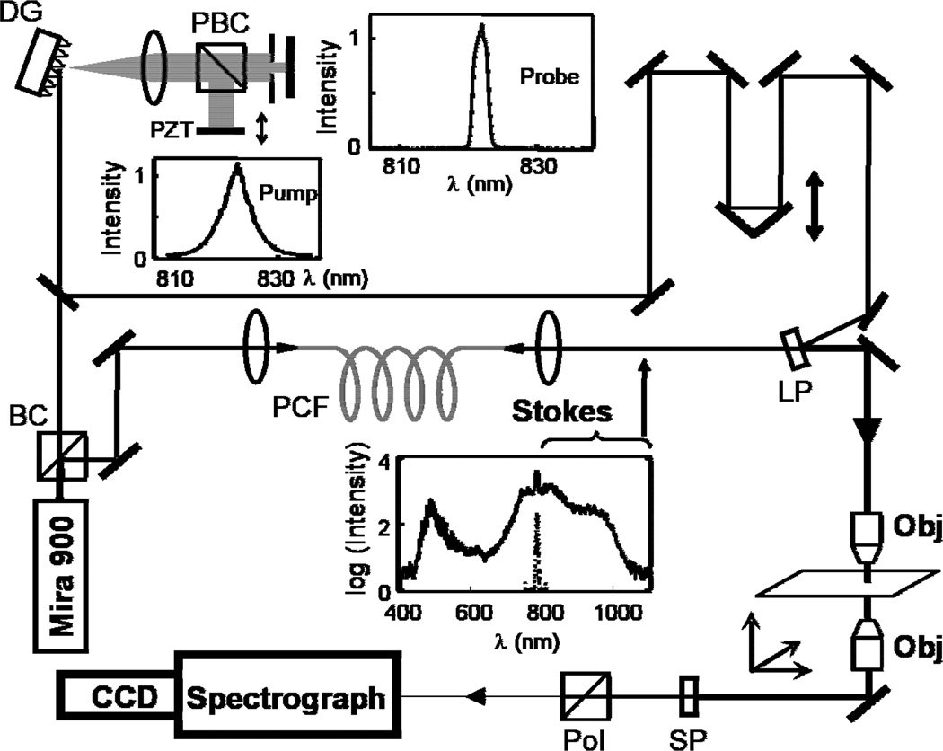
Fig 2.
Experimental configuration: BC, beamsplitter cube; DG, diffraction grating; PBC, polarizing beamsplitter cube; PZT, piezo-electric transducer; PCF, photonic crystal fiber; LP, long wave pass edge filter; Obj, microscope objective; SP, shortpass filter; Pol, polarizer. The inset spectra are (from top) probe, pump (Mira 900 output), and output of PCF. The PCF feed light is arbitrarily scaled and superimposed on the PCF output spectrum.

