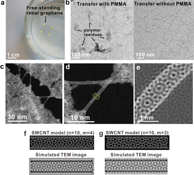
Figure 2.
CNT reinforcement in rebar graphene sheets. (a) A free-standing rebar graphene sheet, highlighted in yellow at the corners, floating on water with 1% butanol by volume. The rebar graphene sheet is ∼1 cm × 1 cm and not precoated with any polymers. Here, butanol was used to lower the surface tension of water and could be removed by vacuum treatment after transferring the rebar graphene sheets onto the target substrates. (b) TEM images indicating that a conventional PMMA-assisted transferred rebar graphene sheet is dotted with polymer residues (left) and the polymer-free transferred rebar graphene sheet that has a clean surface (right). (c and d) ADF-STEM images of rebar graphene suspended on TEM grids, demonstrating that SWCNTs straddle cracks and work to strengthen the rebar graphene sheet. This sample came from a water float that did not contain 1% butanol to lower the surface tension, thus leading to the formation of small cracks in rebar graphene; it is different than the sample in panel a. The bright contrast in the graphene region originates from hydrocarbon contamination absorbed from the air. (e) An atomic-resolution ADF-STEM image of the region of the SWCNT indicated by the yellow region in panel d, showing a clear moirés pattern with a periodicity at ∼0.8 nm. (f and g) Structural models and simulated TEM images of the chiral SWCNT (10, 4) and the chiral SWCNT (10, 3).

