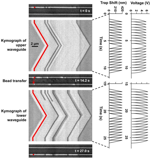
Figure 3. Controlled long range transportation by an nSWAT.
An array of beads (356 nm in diameter, one false-colored) were initially trapped on the upper waveguide and transported in a controlled manner along the waveguide in both directions (Video S1). Subsequently, laser power was switched from the upper to the lower waveguide using the MZI switch and beads were then trapped and transported along the lower waveguide. Each kymograph shows a line scan of an image of the active waveguide (horizontal axis) versus time (vertical axis), with the corresponding voltage applied to the microheater and the resulting phase shift of the standing wave plotted on the right.

