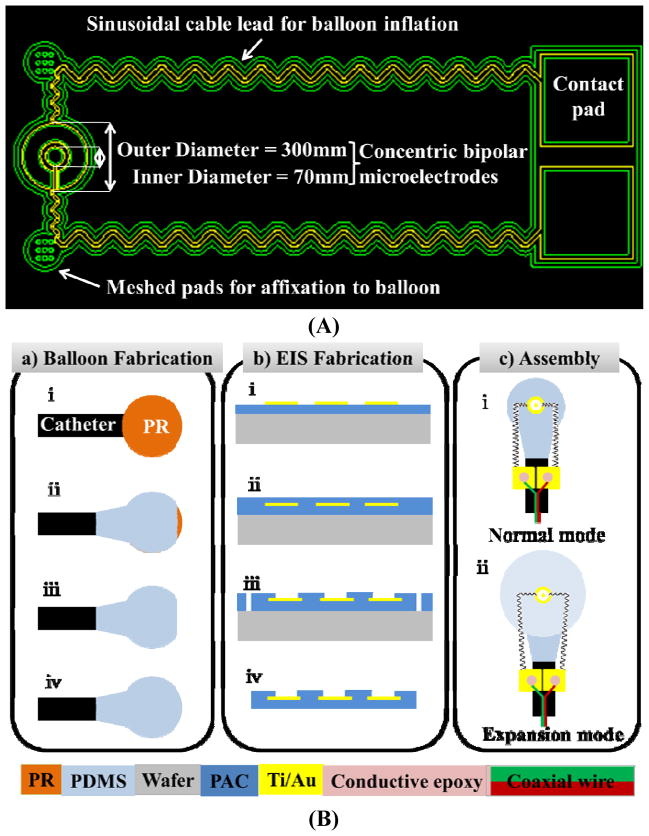
Fig. 1.
(A) The concentric bipolar microelectrodes. The impedance sensor on the left was designed to mount on the surface of the balloon and the contact pads on the right were to affix onto the catheter. The two sinusoidal leads connecting between the contact pads and the impedance sensor were allowed to be stretched in both x- and y-direction in response to balloon inflation. The meshed gluing pads were patterned with 9 opening holes to facilitate affixation to the balloon via the biocompatible glue. (B) Microfabrication of balloon inflatable concentric bipolar microelectrodes. (a) Balloon fabrication: (i) A droplet of photoresist (PR) formed on the tip of a catheter tube. (ii) Silicone partially coated the PR droplet while allowing the tip to be opened. (iii) PR was removed. (iv) The tip was sealed with silicone, resulting in a balloon. (b) Fabrication of the concentric bipolar microelectrode sensor: (i) Standard parylene C (PAC) was deposited and metal was patterned for both the sensor and electrode leads. (ii) A 2nd PAC coating sealed the metal. (iii) At the terminal end of the sensor and the contact pads, lithography was performed, followed by O2 plasma etching of PAC to open the sensor electrodes and the contact pads, and to define the edges of the sensor and the leads. (iv) After lift-off from the substrate, the terminal end of the sensor was completely free-standing. Assembly of the balloon and sensor: (i) The impedance sensor was mounted on the non-inflated balloon by the two meshed gluing pads. The two contact pads were affixed onto the catheter tube. (ii) The inflated balloon stretched the sensor cables in both x- and y-direction.

