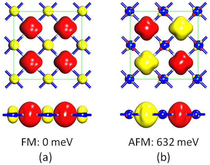
Figure 2. Magnetic coupling configurations of the monolayer CrN.

Top and side views of the optimized geometry and spin charge density isosurface (isovalue: 0.2 e/Å3) of (a) the FM and (b) AFM configurations of the monolayer CrN. Red and yellow isosurfaces correspond to spin up and spin down charge density, respectively. Green squares denote the 2 × 2 supercell.
