
Fig. 2.
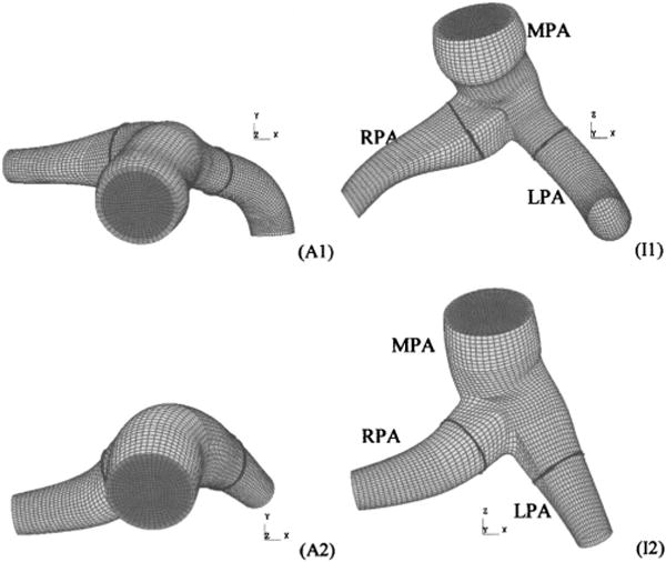
Anterior (Ax) and inferior (Ix) views of four computational meshes derived from patient-specific geometry (exit sections not shown). Light and dark gray surfaces denote the structural domain and fluid inlet, respectively. Thick black lines denote cross-sectional cut locations at which secondary flows and wall shear stress are examined in the results section.