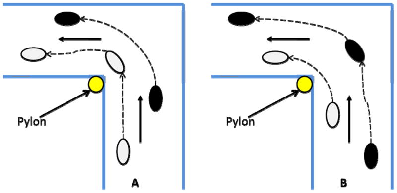
Figure 2.

Representative foot placement for spin (A) and step (B) turns. The grey foot indicates the left foot. The black foot indicates the right foot. (A) For a spin turn to the left, the left foot lands on the force plate. The left leg here is the stance limb throughout the turn. (B) For a step turn to the left, the right foot lands on the force plate. The right leg is the stance limb throughout the turn.
