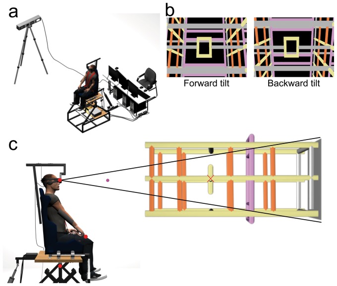
Figure 1. Experimental setup.
a) Global view of the apparatus including the tilting chair, the HMD, the motion tracking system and the cluster of computers. b) Side view of the tilting chair. The sketch represents a subject in the initial standard position with the right arm outstretched in a drainpipe. Red dots represent the markers tracked with the motion capture system. They were positioned on the index fingertip, at eye level, and on the chair axis of rotation. The HMD displayed a visual target (pink dot) located straight ahead and a structured visual background as illustrated in front of the subject. The red cross, which was not displayed to subjects, corresponds to the center of scene rotation. c) Screen captures of the visual scene actually viewed by subjects' right eye when tilted 18 deg forward (left panel) and backward (right panel).

