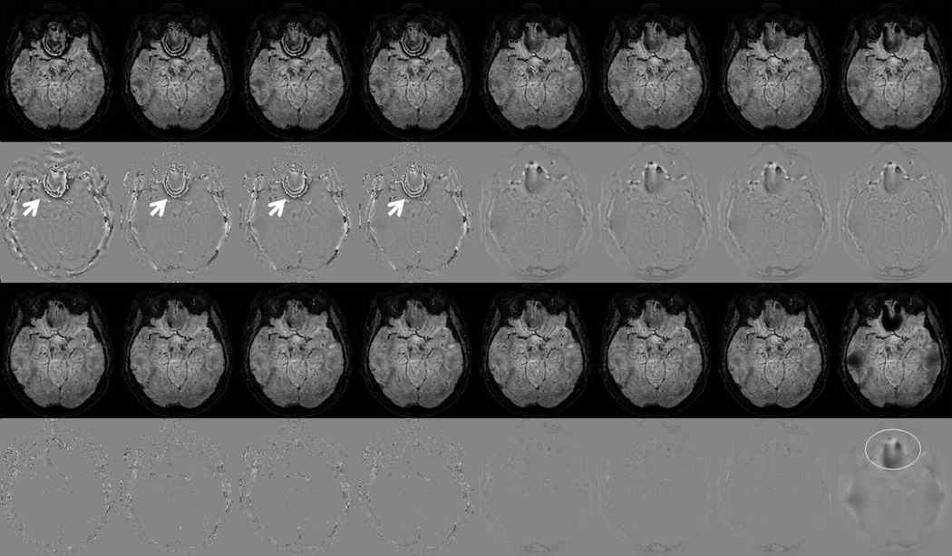
Figure 7.
SWI(row 1,3) and corresponding processed phase(row 2,4) images. Each column represents a different phase processing approaches, from left to right are: Homodyne-rectangular filtering, Homodyne-Gaussian filtering, Homodyne-Hanning filtering, Homodyne-Hamming filtering, phase unwrapping-Gaussian filtering, phase unwrapping-Hanning filtering, phase unwrapping-Hamming filtering and phase unwrapping-smoothing approaches, respectively. First two rows used filter size/smoothing factor of 32/21 pixels. Bottom two rows used filter size/smoothing factor of 80/51 pixels. White arrows point residual phase wrap errors. White circle indicates the present of background gradients due to a relatively large smooth factor.

