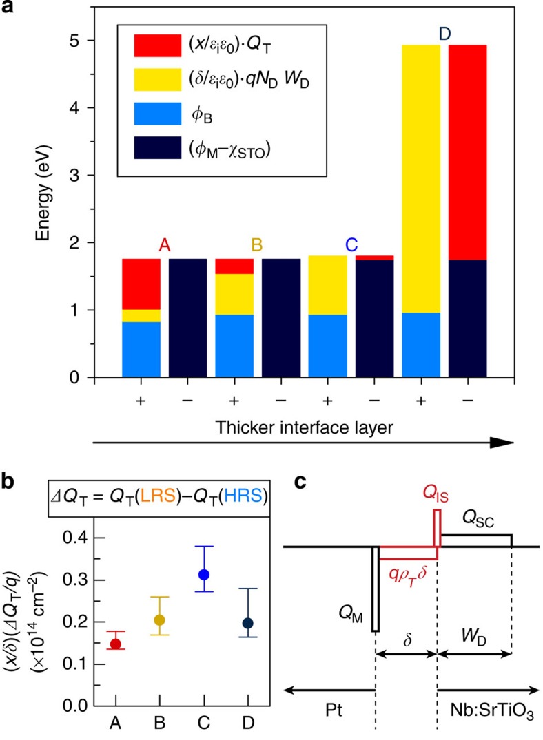
Figure 5. Contributions of trapped and interface charges.
(a) Magnitude of the positive and negative terms (+ and − columns, respectively) in Equation (10) for all junctions in HRS. (b) Calculated modulation of trapped charged centroid during resistive switching, ΔQT=QT(LRS)−QT(HRS). (c) Simplified charge density profile for a Pt/Nb:SrTiO3 junction with interface states and trapped charge in the interface layer.

