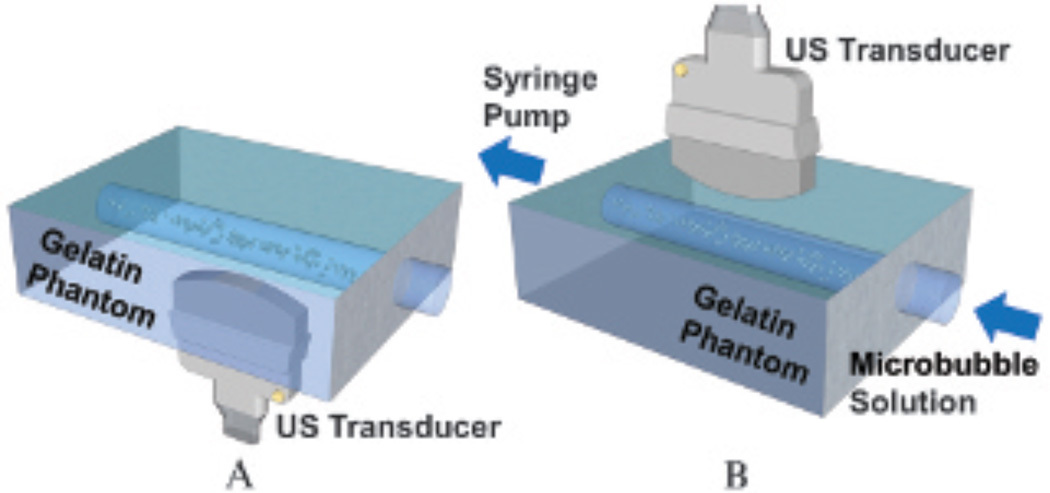
Figure 3.
Flow phantom experimental setups. A, Static fluid channel. Microbubbles were pushed via acoustic radiation force and imaged from underneath the phantom. The top channel wall was at the transducer focal depth of 2 cm. B, Flowing fluid channel. Microbubbles were pushed and imaged from top to bottom. The bottom channel wall was at the transducer focal depth of 2 cm. All fluid channels have a diameter of 4.5 mm. US = ultrasound.

