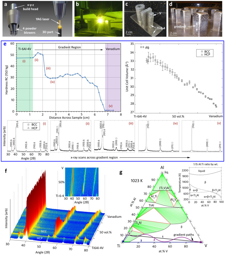
Figure 1. Analyzing a Ti-6Al-4V to V Gradient Alloy.
– (a) Schematic of the laser deposition (LD) building heads used to fabricate gradient alloys. (b) Image of the LD process fabricating several test specimens of the Ti-V gradients. (c) Three gradient alloy specimens; a hollow cylinder, a plate and a beam. (d) Example of a “forest” of gradient alloy posts used to vary gradient compositions. (e) A plot of Rockwell C hardness vs. distance across at Ti-6Al-4V to V gradient alloy where x-ray scans from locations (i–v) are shown below the figure. At right is a plot showing unit cell volume throughout the gradient, as measured from the x-ray peaks. (f) A 3D map of x-ray peaks across the gradient alloy showing the transition from HCP to BCC and the lattice shift of BCC (2D shown in the inset). (g) A Ti-Al-V vertical section at 1023 K. Path (1) is the rule-of-mixtures between Ti-6Al-4V powder and V powder. Path (2) represents a gradient path which transitions from Ti-6Al-4V to pure Ti then to pure V. Path (3) is meant to illustrate a freeform path, where the composition can be changed continuously by mixing Ti, Al and V elemental powder.

