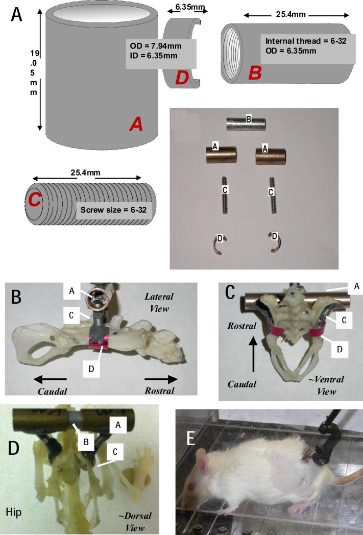
Figure 1. Components and dimensions for pelvic orthosis fabrication, and skeletal placement.
A. Components. Component labels are in italics. A female threaded aluminum standoff (B), a pair of stainless steel screw rods(C), bronze sleeve bearings(A), and aluminum cuffs or c-clamps (D) having an arc of ~190-210 degrees, were used to fabricate the pelvic orthosis. A/C/D are assembled and cemented prior to sterilization for surgery. After insertion, and tightening of implant placement in surgery , A and B are secured to one another with epoxy steel adhesive. B. Lateral View with assembled components labeled. C ~Ventral View, with assembled components labeled. D. ~ Dorsal view on Full rat skeleton with hip/leg visible and components labeled. E Completed implanted assembly in awake rat with a phantom 1.0 robot attached to the A/B assembly.

