
Fig. 3.
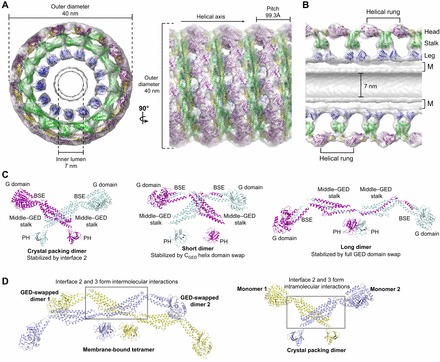
Dynamin assembly and subunit architectures. (A) Pseudo-atomic model of the assembled dynamin polymer (PDB: 3ZYS) that has been derived from computationally fitting GGGMPPCP (purple and yellow; PDB: 3ZYC), the MxA stalk (green, PDB: 3LJB) and the human dynamin 1 PH domain (blue, PDB: 1DYN) into the 12.2 Å GMPPCP-stabilized ΔPRD cryo-EM map (gray, EMD-1949). End-on and side-on views are shown in the left and right panels, respectively, with the dimensions and helical axis marked. (B) Cross-section view of the assembled dynamin polymer oriented as in A. The G domain, middle–GED stalk and PH domain occupy the head, stalk and leg density regions, respectively. The inner luminal diameter is indicated. M, membrane bilayer. (C) Different model representations of the minimal dynamin dimer building blocks. Monomers are colored purple and cyan. Left, dimer based on crystal packing (PDB: 3ZVR) that is stabilized by interface 2 interactions; center, X-shaped short dimer based on chemical crosslinking and computational docking that is stabilized by a domain swap of the CGED helix; right, M-shaped long dimer based on chemical crosslinking and computational docking that is stabilized by a full domain swap of the GED. (D) Putative structure of membrane-bound dynamin tetramer. Underlying dimers are colored yellow and light blue. This model assumes the entire GED is domain-swapped in each monomer (see text). In this context, portions of interface 2 and 3 mediate inter-dimer interactions (gray box). The structure of the crystal packing dimer is shown on the right for comparison with each monomer colored yellow and light blue. Note that in this case, interface 2 and 3 form intra-dimer interactions (gray box).