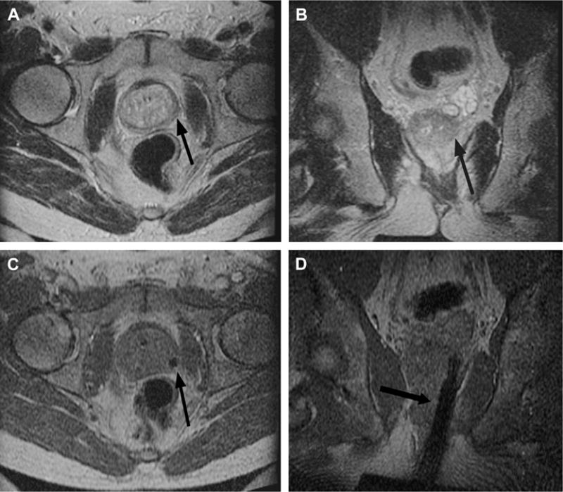
Fig. 6.

Imaging before and during MR imaging–guided prostate biopsy. Axial (A) and coronal (B) T2-weighted spin-echo sequence outline areas to be biopsied. In this example, an area in the left midgland is demonstrated (arrow), reformatted to the same spatial location as the corresponding real-time axial (C) and coronal images (D) taken during needle insertion. The biopsy needle is seen in cross section as a circle of low-signal intensity (arrow) on the axial gradient-echo real-time image (C) and as a longitudinal area of low-signal intensity (arrow) on the coronal gradient-echo real-time image (D).
