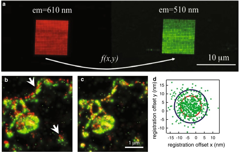
Fig. 4.

An illustration of the image registration procedure to align images from different color channels. a An image obtained by integrating the images in the green and red channel of a fiducial scanned across a square grid with a size of ~10 µm. b An overlay of the red and green PALM images of a membrane patch of a cell that expressed the protein SrcN labeled with a fusion construct of psCFP2 and mEos2, prior to image registration and c after image registration. d A scatter plot of the residual offset x g − x r and y g − y r, with x g and x r being the x-coordinates in the green and red channel respectively, and y g and y r being the y-coordinates in the green and red channel respectively. The blue circle has a radius of 10 nm, the red circle has a radius given by , with σ g and σ r being the localization precisions in the green and red channel respectively. The residuals were extracted from the trajectory of a fluorescent bead with 100 nm diameter, immobilized on the coverslip and imaged during a time lapse movie. Adapted from Annibale 2012 and Annibale et al. 2012
