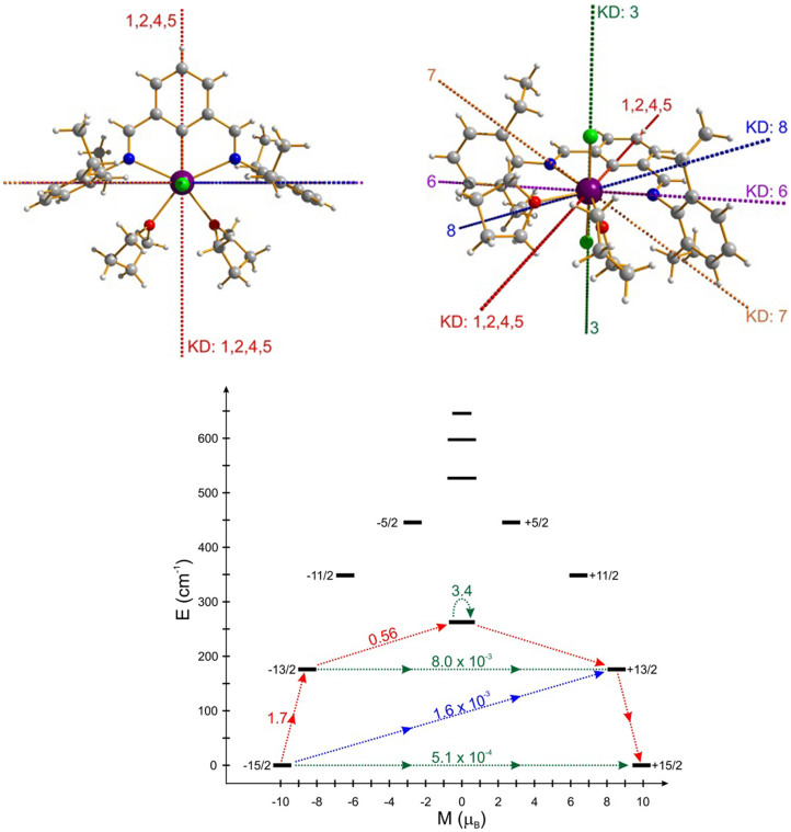
Figure 3. Low-lying electronic structure for DyNCN.
(Top) Anisotropy axes in eight lowest Kramers doublets at the Dy site of DyNCN (KD: 1–8 ranked in order of the energy from ground state to the seventh excited state as shown in below scheme). The red dashed line corresponds to the anisotropy axis of KD: 1, 2, 4 and 5; the green dashed line shows the anisotropy axis of the second excited KD (KD 3 lying at 262 cm−1). (Bottom) Magnetization blocking barrier of the DyNCN. The black lines represent the energy levels of the ground multiplet J = 15/2 aligned according their magnetic moment on the C2 symmetry axis. The arrows represent the averaged matrix element of the transversal magnetic moment connecting the corresponding states, given as (|μx| + |μy| + |μz|)/3. The red arrows show the most probable path for the magnetic relaxation at high temperatures.

