Abstract
Dynamic nuclear polarization (DNP) is an NMR-based technique which enables detection and spectral characterization of endogenous and exogenous paramagnetic substances measured via transfer of polarization from the saturated unpaired electron spin system to the NMR active nuclei. A variable field system capable of performing DNP spectroscopy with NMR detection at any magnetic field in the range 0 - 0.38 T is described. The system is built around a clinical open-MRI system. To obtain EPR spectra via DNP, partial cancellation of the detection field B0NMR is required to alter the evolution field B0EPR at which the EPR excitation is achieved. The addition of resistive actively shielded field cancellation coils in the gap of the primary magnet provides this field offset in the range of 0–100 mT. A description of the primary magnet, cancellation coils, power supplies, interfacing hardware, RF electronics and console are included. Performance of the instrument has been evaluated by acquiring DNP spectra of phantoms with aqueous nitroxide solutions (TEMPOL) at three NMR detection fields of 97 G, 200 G and 587 G corresponding to 413 kHz, 851.6 kHz and 2.5 MHz respectively and fixed EPR evolution field of 100 G corresponding to an irradiation frequency of 282.3 MHz. This variable field DNP system offers great flexibility for the performance of DNP spectroscopy with independent optimum choice of EPR excitation and NMR detection fields.
Keywords: proton MRI, EPR imaging, free radicals, oxygen, image co-registration, in vivo NMR, in vivo EPR
1. Introduction
Dynamic nuclear polarization (DNP) is based on the Overhauser effect, predicted by Overhauser [1] and then demonstrated experimentally by Carver and Slichter [2]. The DNP effect was predicted by Overhauser in solids [1], but later Hausser and Stehlick demonstrated the effect in liquids, focusing on studying molecular interactions between electrons and protons in free radical solutions [3]. The EPR line of the paramagnetic probe is irradiated and on partial saturation of the electron spin system there is a transfer of polarization from the unpaired electron to the water protons. The resulting enhancement of the NMR signal is given by the Overhauser enhancement factor E,
| (1) |
where Sz and S0 are the NMR signals acquired with and without EPR irradiation respectively. The Overhauser enhancement of the paramagnetic probe can be recorded as an image showing spatial distribution of the free radical in the sample. This technique is called proton electron double resonance imaging (PEDRI) at fixed field and was first demonstrated by Lurie et al. [4]. The paramagnetic sample is placed in a constant magnetic field and the unpaired electron is excited with microwave radiation at the corresponding electron resonance frequency, and this is followed by conventional NMR image acquisition producing a map of free radical distribution. A major challenge with this technique is that the EPR irradiation frequency is 660 times the proton excitation frequency. This high resonance frequency would result in non-resonant power deposition in the sample if applied at high magnetic fields typical for MRI. In order to use the Overhauser effect in animals one can perform field-cycled PEDRI (FC-PEDRI) wherein two magnets which can work in opposition to each other are used to lower the magnetic field for the time of EPR irradiation and then to raise the magnetic field back for NMR detection [5].
The spectroscopic variant of FC-PEDRI that allows observing EPR-like resonances of the paramagnetic probe, from the proton NMR spectra via the Overhauser enhancement is called field-cycled DNP (FC-DNP) and has been described in the literature [6, 7]. The technique is useful in studying low concentrations of paramagnetic species in biological samples. The FC-DNP spectrum is acquired by varying in small steps the magnetic field B0EPR at which the electron excitation (at constant electron frequency and constant power) is applied [6, 7], each time returning to a fixed magnetic field B0NMR in order to record the NMR signal after the electron excitation. The NMR signal amplitude is then plotted against B0EPR to produce an FC-DNP spectrum of the paramagnetic probe. During the course of the field sweep, changes in the NMR signal reveal the positions and intensities of the sample's EPR resonances resulting from the polarization transfer from the electron to the proton spin that only occurs when the EPR resonance condition is satisfied. Thus the FC-DNP spectrum resembles the EPR absorption spectrum of the paramagnetic probe, although the FC-DNP line-widths of the resonances are typically much broader [6].
The measured spectrum can be correlated directly with the EPR resonances of the paramagnetic probe, thus providing EPR spectral information. This information can be used for measurements of a variety of biologically relevant parameters such as oxygen concentration and pH, with the use of appropriate oxygen and pH sensitive paramagnetic probes [8]. FC-DNP spectroscopy and PEDRI has also been used to study molecular dynamics [9], and Nicholson et al. demonstrated the variation of Overhauser enhancement with proton mobility [10]. Nestle et. al have used PEDRI for the first time in environmental science applications to study free radical transport in environmental matrices and sediment samples [11].
DNP imaging and spectroscopy studies have been performed at various NMR detection field strengths: 15 mT, 20 mT, 59 mT and 450 mT [12, 15, 5, 14]. These prior systems have been built utilizing either low field resistive magnets, permanent magnets or superconducting magnets all of which enable only a narrow range of Bo fields. A previously described commercial system [12, 13] built by Philips Research Laboratories (Hamburg, Germany) utilizes a human whole-body air-cooled electro-magnet with a horizontal bore and a maximum operating field of 15 mT. Although the NMR detection field can be ramped up to higher values, the capabilities of the current power supply as well as magnet heat dissipation do not permit values of more than 15 mT [12]. The field in the same magnet is ramped down to 8.1 mT in order to establish the low EPR irradiation field [13].
Another variant of the field-cycling system consists of a human whole body 59 mT permanent magnet to establish the main field [5] with the cancellation coils embedded within the main magnet. This design is superior in terms of minimizing mutual interaction between the two magnets; however, one is restricted in the fixed field strength that is determined by the permanent magnet. Another design uses a superconducting magnet to establish the main magnetic field of 450mT and coaxial cancellation coils to achieve field-cycling [14]. A limitation of this system would be the higher costs of running a superconducting magnet and, especially, the inability to vary the detection field from one experiment to the other.
The conversion of a whole body 0.38 T clinical scanner to a fixed-field PEDRI system has previously been reported by our group [15]. Fixed-field PEDRI is one of the multiple imaging modalities that is based on the 0.38 T primary magnet described here. The fixed-field system is capable of performing biological PEDRI applications at 20 mT [16, 17, 18]. However, one of the problems with fixed-field PEDRI is that the chosen field-strength should be low enough to minimize non-resonant power deposition in the biological sample and the magnetic field should also provide adequate NMR signal to ensure good image quality. The choice of field strength generally a compromise since even at 20 mT the electron resonance frequency is 567 MHz which results in considerable tissue heating over the course of an imaging experiment. As mentioned earlier field-cycling can help solve this problem [5]. However, most systems discussed above have used a fixed NMR detection field and are limited in terms of the amount of field-cycling that can be achieved thereby indicating a need for a variable field system that is capable of operating at multiple NMR detection fields and EPR irradiation fields.
Such a system if available would help determine the optimum combination of EPR irradiation field and NMR detection field that would result in maximum free radical detection sensitivity and high NMR signal-to-noise ratio. Also, one would require a variable field system that would be capable of varying both the NMR and EPR irradiation field over a large range (0-100 mT). In order to further adapt the Overhauser effect for biomedical research, and to be able to perform field-cycled PEDRI at variable fields, a new system based on a resistive iron core main magnet and resistive field cancellation coil set enabling measurements at detection magnetic fields of 0 – 0.38 T with field-cycling capability of up to 0.1 T. This arrangement uniquely enables performance of DNP spectroscopy at variable and optimized combinations of NMR detection field and EPR irradiation field. The system we describe is therefore novel, highly flexible with a number of advantages compared to the above-mentioned PEDRI systems [5, 12, 13, 14].
A 0.38 T clinical open-MRI scanner has been transformed by the addition of a secondary magnet. The secondary electromagnet in the form of low inductance planar coils has been built into the gap of the primary magnet. The secondary magnet can provide a vertical magnetic field offset of up to 100 mT to perform EPR irradiation at low magnetic field followed by high field NMR detection. To preserve the original functionality, the secondary electromagnet has been designed as a movable insert. Thus, the MR imager can be rapidly converted from conventional MRI acquisition to fixed-field PEDRI or DNP spectroscopy with field sweep capability about a chosen NMR detection field B0NMR in minimal time. The design and evaluation of this instrumentation are described in the following sections.
2. Materials and Methods
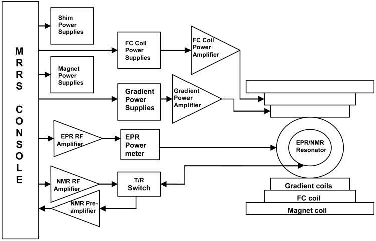
The system block diagram is shown in figure 1. In order to achieve the field sweep necessary for low-field DNP spectroscopy the primary magnetic field of the clinical MR system is partially cancelled by planar field cancellation coils referred to as the secondary coil placed at the center of the gap of the primary magnet. The details of the magnet design and their respective power supplies and power amplifiers, the various elements of the RF chain and the console used to control the secondary magnet and DNP data acquisition are presented in the following sections.
Fig.1. General block diagram of the variable-field DNP spectroscopy system.
2.1 Primary magnet and power supply
The main magnetic field which is vertical is generated by a water-cooled iron core Resonex 5000/Paradigm resistive magnet (Resonex Corp., Sunnyvale, CA) with a gap of 50 cm between the magnet poles with the shims in place. FC-DNP spectroscopy requires that the NMR detection field B0NMR be highly homogenous and stable. This is achieved with a set of 24 active shims that provide homogeneity of better than 50 ppm over a sample of size 50×40×40 cm placed at its isocenter, and better than 20 ppm over a 25×20×20 cm sample volume. The magnet is powered by a Danfysik MPS 854/SYS 8000 power supply (Danfysik, Jyllinge, Denmark) that can provide current up to 1980 A required to establish a magnetic field of 0.38 T. While operating as a conventional MRI scanner, the magnetic field is current controlled and its stability relies on the high precision manually adjustable reference voltage. Current regulation provides high stability better than 0.5 ppm/hr of the current and hence magnetic field. To be able to maintain the high stability of the primary magnetic field as occurs at 0.38 T even at low fields (≥10 mT), a modification to the magnet power supply's control circuitry was made, the details of which have been described [15].
2.2 Secondary magnet and power supply
The secondary magnet is used for partial cancellation of the main magnetic field which occurs in small steps to enable the field sweep necessary for spectroscopy. A planar low inductance coil (Tesla Engineering, West Sussex, UK) placed in the gap within the primary electromagnet magnet is used for this purpose. A photograph of the dual magnet assembly is shown in figure 2. Its low inductance of 11 mH allows rapid current switching (current rise time: 0-308 A (∼0.1 T) in 14 ms) during acquisition of each point in the DNP spectrum. The cancellation coils also have an integrated gradient coil which is not used in the DNP spectroscopy studies but has been used in EPR/NMR co-imaging research [19] and can be used for future FC-PEDRI applications. The secondary coil is actively shielded to minimize the eddy currents that result in the primary electromagnet when the current in the secondary coils is ramped up and down to perform field cancellation.
Fig.2. Mechanical layout and photograph of the variable-field DNP spectroscopy system.
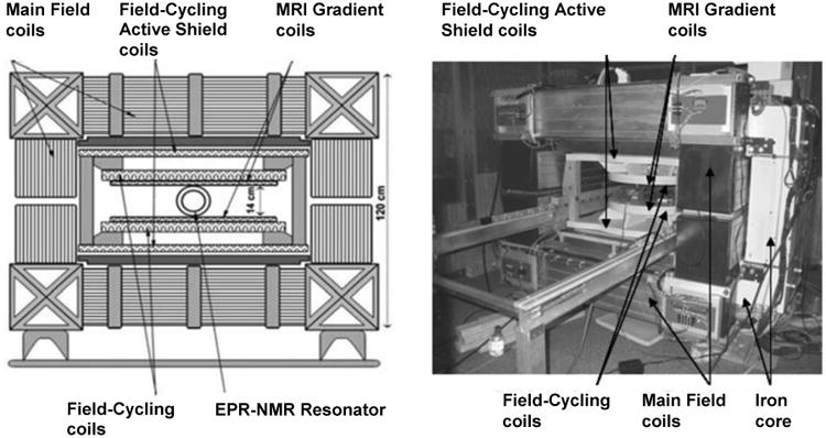
The planar secondary coils are 650 mm in diameter with the nominal gap between the upper and lower coils being 180 mm. The main electrical parameters of the cancellation coils are as follows: DC resistance <360 mΩ; field strength per unit current 325 μT/A; the maximum current for safe operation without the risk of overheating is 312 A; this corresponds to a maximum cancellation field of 0.1 T. Any heat generated is removed from the water cooled cancellation coils by an Eaton-Williams TE 20411 heat exchanger (Eaton-Williams Group Ltd, Kent, UK) which then rejects the heat to the site's chilled water supply.
The power supply that drives the secondary coil consists of a Copley 266 power supply amplifier (Copley Controls, MA, USA) rated at 350 V, 250 A which is powered by two 15 kW DC power supply (Lambda EMI, NJ, USA) connected in parallel. The output current of the Copley power supply amplifiers can be ramped up from 0-207 A in 8 ms which corresponds to a 0-670 G change in the vertical field produced by the cancellation coils. A positive current results in a downward field shift and negative current results in an upward magnetic field shift. The secondary coil is mounted on a roller and rail mechanism to slide in and out of the magnet providing ease of interfacing and setup along with convenient access for service and further modifications of the Resonex scanner. The rails were made out of fiber-glass/epoxy composite (Grade G-10/FR4 Garolite) in the form of rectangular bars and can be extended to both ends of the magnet for easy displacement of the cancellation coils to clear the magnet gap for non-DNP experiments and easy maintenance.
2.3 Magnetic field instability and correction
The secondary coils are actively shielded to minimize coupling between the two magnet windings; however, there is a leakage current in the primary magnet due to imperfect shielding that causes the secondary coils to produce fluctuations in the B0 field. Therefore a correction in the form of a pre-emphasis during both ramp-up and ramp-down has been superimposed on the analog trapezoidal input to the power supply amplifiers. In order to calculate the amount of pre-emphasis required, the magnetic field produced at the center of the cancellation coils for a trapezoidal input were recorded by placing a Hall probe of an analog gauss meter (LakeShore, OH, USA, model 450) at the center of the cancellation coils. The magnetic field variations were viewed on an oscilloscope and recorded electronically to enable data processing on a computer.
Curve-fitting of the magnetic field variation data yielded correction factors that were used to derive the pre-emphasized analog input signal that would be used to drive the cancellation coils. From phenomenological point of view, the system should behave similar to a dampened oscillator, hence the fitting equation of the field profile should include a superposition of sine and cosine terms which are modulated by an exponential decay. The main parameters such as phase, frequency and amplitude were then fitted using ORIGIN 5.0. (http://www.originlab.com). The improvement in the field stability was again recorded using a Hall probe and oscilloscope and the corrected field profile is shown in figure 3.
Fig.3.
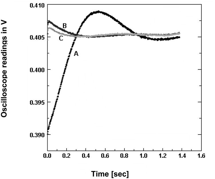
Effect of pre-emphasis on the magnetic field instability. An improvement in magnetic field stability by pre-emphasis of the current waveforms driving the field-cycling coils was observed. (A) No correction applied (B) Pre-emphasis based on a first order differential equation fit of the instability (C) Pre-emphasis based on a second order differential equation fit of the field instability. The magnetic field variation was detected by a gauss meter placed at the center of the magnet. The y-axis shows the measurements recorded on the oscilloscope that was connected to the gauss meter (1 mV = 1 G)
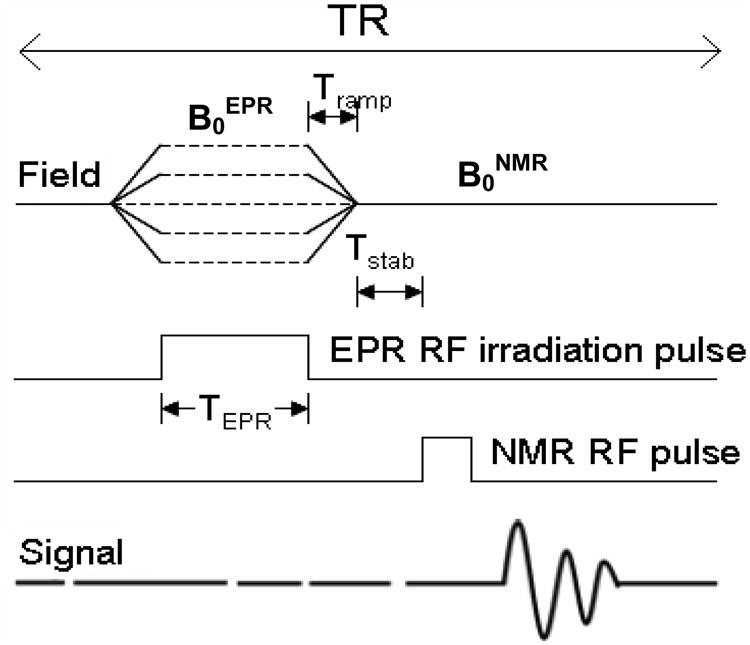
With the use of the above-mentioned pre-emphasis the current has to be ramped up and down in the field-cycling coils with a Tramp (as depicted in figure 4) of at least 40ms. Soon after ramping down the current in the field-cycling coils, the field is allowed to stabilize for a period of time equal to Tstab after each EPR excitation and before NMR detection. Tstab is about 200 ms in case of ΔB ≈ 300 G where ΔB = B0NMR-B0EPR. The field is also allowed to settle to B0NMR soon after the NMR acquisition and before ramping up the current in the cycling coils to establish a low field for the EPR excitation.
Fig.4. FC-DNP spectroscopy pulse sequence diagram.
2.4 Pulse sequences
The FC-DNP pulse sequence is depicted in figure. 4. The field sweep is accomplished by varying the field at the sample incrementally in small steps to enable irradiation of the electron spins. The pulse sequence begins with the switching of the magnetic field from B0NMR to B0EPR in a time equal to Tramp. EPR irradiation of the electron spin at B0EPR for a time TEPR occurs at this low field. This is followed by the ramping up of the field to B0NMR for detection of the NMR signal. This sequence is repeated by increasing B0EPR in steps of 0.2 G to 1.0 G (typically) to achieve the field sweep necessary for acquiring the FC-DNP spectrum.
2.5 NMR console
The system is equipped with a customized MRRS MR 5000 console (MR Research Systems, Surrey, UK). The console is used to control the imager namely the gradient hardware, the RF system, field-cycling coils, image acquisition and post-processing except for the magnet shim coils and the magnet power supplies which are under the control of the Resonex console. The console software runs on a Pentium computer with a Windows NT operating system. The software comprises a digital signal processor, pulse sequence programmer based on C++ platform, RF waveform generator and gradient waveform controller. A 12-bit MR3031 digital-to-analog-converter was used to generate the necessary analog outputs required to drive the FC coils. The maximum field resolution provided by the 12-bit board is 0.2 G. Modifications in existing pulse sequences were made in order to implement the FC-DNP acquisition sequence shown in figure 4.
2.6 RF system
The MRRS console includes the NMR and EPR RF pulse generator and synthesizer. The NMR excitation pulse generated by the console is sent to the ENI LP-10 power amplifier (ENI Ltd, Rochester, NY) and then via the active Resonex transmit/receive (T/R) switch to the RF coil. The detected NMR signals from the RF coil are directed by the T/R switch to a home-built low frequency pre-amplifier [15] and then to the NMR console for demodulation at the receiver. The EPR excitation signal is a hard pulse generated by the console which is used to modulate the auxiliary output of the synthesizer (282 MHz) and is then amplified by a Kalmus 7150LC power amplifier (Amplifier Research, Souderton, PA, USA). The EPR RF amplifier has a bandwidth of 20-1000 MHz and a maximum output power of 150 W. On amplification it is passed on to the EPR resonator via a Bird 4391A power meter (Bird Electronic Corp. Solon, OH, USA) which is used to monitor the forward power to the resonator during the experiment.
The DNP experiment requires a dual resonance coil/resonator assembly for NMR transmission and reception and EPR transmission. In order to maximize NMR sensitivity and signal reception the NMR resonator is in closer proximity to the sample under study and is surrounded by the EPR transmit system. The EPR resonator is based on a modified Alderman-Grant design [20] which utilizes a quartz tube for greater thermal stability and electrical coupling circuitry for independent tuning and matching adjustments. The resonator has been constructed from copper sheet 0.15 mm thick that is placed over a quartz tube of outer diameter 70 mm and inner diameter 67 mm.
Three NMR solenoidal coils of the same outer diameter 35.5 mm and inner diameter 32 mm and length 36 mm have been constructed each with different number of turns ‘N’ and different diameter of copper wire ‘φ’. FC-DNP spectra were acquired at the same EPR magnetic field B0EPR but using three different NMR detection fields B0NMR namely 97 G, 200 G and 587 G corresponding to NMR frequencies of 413 kHz (N = 50, φ = 0.37 mm, φ with insulation = 0.89 mm), 851.6 kHz (N = 24, φ = 1 mm, φ with insulation = 1.5 mm) and 2.5 MHz (N = 20, φ = 1 mm, φ with insulation = 1.5 mm) respectively. The resonator assembly has been constructed such that the NMR coils can be changed as required for a given NMR detection frequency, without disturbing the EPR resonator.
3. Results and Discussion
3.1 Evaluation of the field stability during DNP measurements
Preliminary experiments showed that introduction of field cycling had a significant effect on the performance of the system, due to the imperfect shielding of the field cancellation coils. In order to evaluate the performance of the cancellation coils after implementing the field correction waveforms as mentioned in the earlier sections, the baseline NMR signal from a sample of 1 mM TEMPOL nitroxide (4-hydroxy-2, 2, 6, 6-tetramethylpiperidine-1-oxyl) has been recorded at three NMR detection fields B0NMR namely 97 G, 200 G and 587 G without the use of cancellation coils (no field-cycling).
The measured signal was then compared with the baseline NMR signal in the regions apart from the triple resonances of the nitroxide observed in the subsequent FC-DNP experiments. The magnitude of the NMR signal in the DNP spectrum was within ± 20 % of the NMR signals measured with no field-cycling as explained previously, indicating the effectiveness of the field correction approach.
3.2 FC-DNP at variable NMR detection fields
In order to evaluate the performance of the variable magnetic field FC-DNP system phantom studies with 1 mM aqueous solutions of TEMPOL have been performed. A glass tube 8 mm in diameter containing TEMPOL has been used to obtain the triple resonance FC-DNP spectrum of nitroxide. The EPR irradiation field sweep from 70 G - 130 G is performed in steps of 0.36 G in each experiment; however, the NMR detection field B0NMR is varied in each experiment (97 G, 200 G, 587 G) to observe the change in Overhauser enhancement as a function of B0NMR. The EPR irradiation frequency at ∼100 G remains constant at 282.3 MHz. The NMR frequencies at 97 G, 200 G and 587 G were 413 kHz, 851.6 kHz and 2.5 MHz respectively. The repetition time for the FC-DNP pulse sequence is TR=1300 ms.
A spectroscopy data acquisition program written in Visual Basic has been used to visualize the FC-DNP data. Figure 5 shows the three DNP spectra acquired at the same EPR magnetic field but variable NMR magnetic fields. Before proceeding with the discussion of the results it is important to define the two main factors that affect the measured enhancement. First and foremost is the dependence of enhancement on the EPR saturation parameters which is represented by the following relationship,
Fig.5.
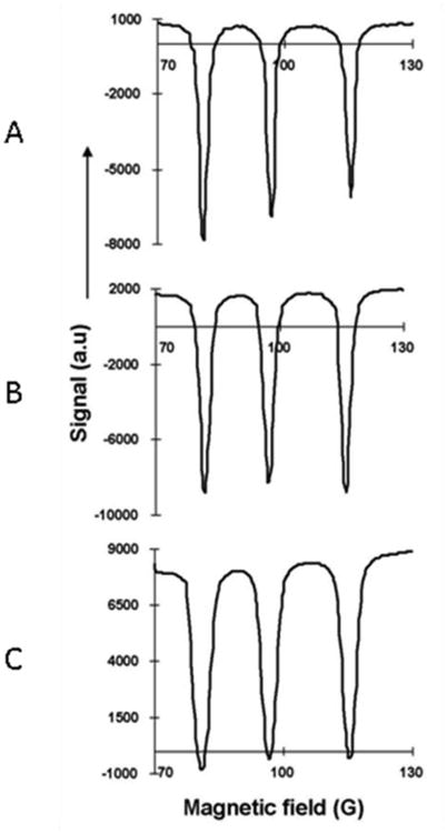
Variation of Overhauser enhancement with change in NMR detection field. DNP spectra of 1mM TEMPOL at multiple NMR detection fields (A) B0NMR = 97 G, (B) B0NMR = 200 G, (C) B0NMR = 587 G and same EPR magnetic field corresponding to a frequency of 282.3 MHz, EPR pulse duration of 500 ms and EPR irradiation power of 5 W and TR=1300 ms. The resolution of the field sweep was 0.5 G.
| (2) |
where ρ is the coupling factor (-1 ≤ ρ ≤ 1/2, with ρ =1/2 for dipole-dipole interaction), f is the leakage factor (0 ≤ f ≤ 1), s is the saturation factor (0≤ s ≤ 1), n is the number of hyperfine lines in the EPR spectrum (n = 3 for a nitroxide free radical) and γe and γp are the electron and nuclear gyromagnetic ratios. Secondly DNP enhancement also has a time-dependence [21]. Once the EPR irradiation pulse is switched on, the nuclear magnetization builds up at a rate determined by the NMR longitudinal relaxation time, T1 [22]. This time dependence of the enhancement factor can be represented by the following relationship,
| (3) |
where A(∞) is the asymptotic value of the DNP factor, given by A(∞) = Emax-1 where Emax the maximum enhancement factor that can be observed in a sample of high free radical concentration provided that the complete saturation of the EPR resonance has been achieved. In case of a nitroxide with triple resonance Emax= -109. Since the build-up of magnetization in the nuclear spin system or the enhancement is a function of the nuclear T1, on switching off the EPR irradiation the decay of the enhanced magnetization is also a function of T1.
In this study, the NMR signal was acquired 200 ms after completion the EPR excitation in each of the three cases. As a result, we would expect that the depth of the enhancement (in arbitrary units) observed in each case with fixed EPR saturation parameters would be similar. The depth of enhancement has been calculated as the baseline-to-peak value of the EPR resonance with maximum depth in each case. The average of the baseline-to-peak values (for each of the three cases wherein ΔB = -3 G, 100 G and 487 G) of the maximum EPR resonance was found to be 9267 ± 1334 a.u. The power reflected from and delivered to the resonator may change during the course of the experiment and this could be one of the reasons for the variation in the depth of each resonance in the DNP spectrum. The variation of the depth of enhancement about the average value between the three cases could be attributed to the field instability that exists during EPR excitation and NMR detection as ΔB = B0NMR-B0EPR increases.
3.3 Sensitivity of the FC-DNP system
In order to test the system sensitivity multiple phantoms were constructed with various concentrations of TEMPOL free radical in aqueous solution and the variation of Overhauser enhancement with concentration was observed. The FC-DNP spectra were recorded at B0NMR = 400 G and EPR irradiation frequency 276.7 MHz, with excitation pulse duration of 500 ms, power of 6 W and a TR=1050 ms. The FC-DNP spectra for TEMPOL concentrations 62.5 μM, 125 μM, 0.25 mM and 0.5 mM and the corresponding Overhauser enhancement E (0.74, 0.51, 0.07, -0.84) in each case is indicated in figure 6. The enhancement E was calculated as the ratio of the enhanced NMR signal at the EPR resonance peak to the non-enhanced baseline NMR signal.
Fig.6.
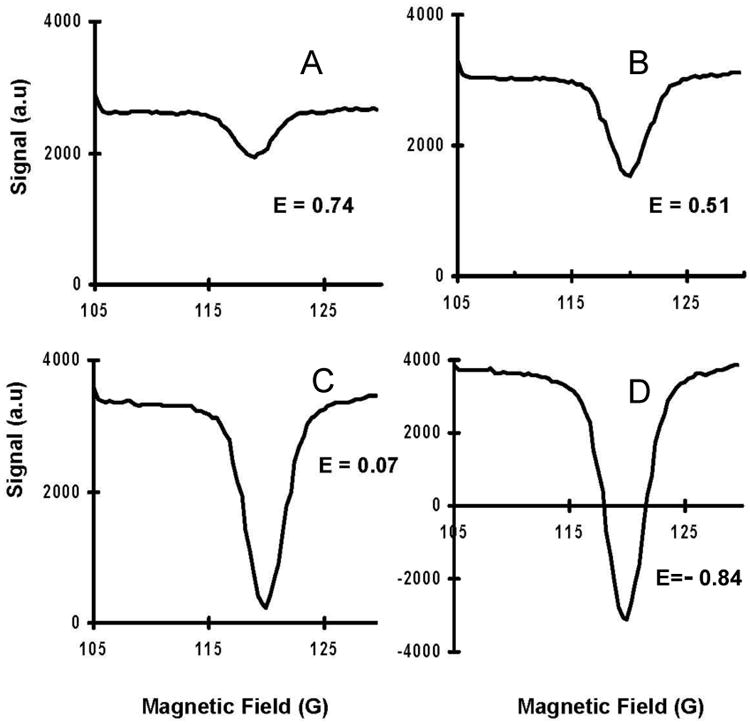
DNP spectra of various concentrations of TEMPOL (A) 62.5 μM (B) 125 μM (C) 250 μM (D) 500 μM. Overhauser enhancements are shown on corresponding panels. Spectra was acquired at B0NMR = 400 G and EPR irradiation frequency of 276.7 MHz, EPR pulse duration of 500 ms and EPR irradiation power of 6 W and TR=1050 ms. The resolution of the field sweep was 0.36 G
From Eqn. (2), it is clear that Overhauser enhancement has a linear dependence on concentration of the free radical under study which is also observed in the experimental data (figure 6). 62.5 μM is the minimum concentration that has been tested with an EPR excitation frequency at 276.7 MHz and B0NMR at 400 G corresponding to a ΔB = 300 G and resulted in a peak-to-noise ratio (PNR) of 48. The PNR was calculated as the ratio of the depth of enhancement (difference in the NMR signal between the enhanced (maximum Overhauser enhancement) and non-enhanced regions of the spectrum) to the standard deviation of the noise in the non-enhanced parts of the spectrum. An increase in EPR irradiation power may allow detection of even lower nitroxide concentrations, but since this study limits the use of EPR irradiation power to levels that may be used in studying biological samples the EPR power levels were restricted to 6 W.
The observed Overhauser enhancement can be improved by increasing the EPR irradiation time. In order to achieve high Overhauser enhancement, TEPR should be at least 3T1 of the sample. The T1 of a 50 μM TEMPOL free radical solution is about 2.5 s [5], and the FC-DNP data presented here were acquired with TEPR =500 ms. Since our main focus would be on biological applications of DNP an EPR irradiation time of 500 ms has been used to ensure minimal power deposition.
4. Conclusions
A novel variable field Field-Cycling instrumentation for DNP spectroscopy has been developed and tested. This utilizes a set of water-cooled resistive coils positioned inside the large resistive iron core magnet. The unique feature of the instrument is that it enables the independent choice of EPR excitation field B0EPR and proton detection field B0NMR that can be adjusted for the needs of a given experiment. It allows performing DNP experiments at any detection field in the range of 0 - 0.38 T of the main magnet with capability of 100 mT field-cycling. Implementation of the magnetic field instability correction allows field ramping in less than 40 ms. Since this Tramp of 40 ms is significantly less than typical in vivo tissue T1 relaxation times, the measured Overhauser enhancement factors are not significantly affected by the delay between EPR irradiation and signal measurement – either in imaging (FC-PEDRI) or in spectroscopic (FC-DNP) experiments. The multi-modal nature of the apparatus also allows performing low-field MRI, high-field MRI, EPR-NMR co-imaging [21], fixed-field PEDRI [15, 16, 17, 18] and variable-field FC-DNP spectroscopy with minimal time for switching between each modality. We believe that this instrument will be useful in the application of Overhauser imaging techniques for in-vivo animal studies. The instrument will be indispensable for study of the effect of variable amounts of field-cycling on the Overhauser enhancement and how one can optimize the choice of EPR excitation and NMR detection field for a given biomedical application.
Acknowledgments
This work was supported by NIH Research Grants EB4900 and EB0890.
Footnotes
Publisher's Disclaimer: This is a PDF file of an unedited manuscript that has been accepted for publication. As a service to our customers we are providing this early version of the manuscript. The manuscript will undergo copyediting, typesetting, and review of the resulting proof before it is published in its final citable form. Please note that during the production process errors may be discovered which could affect the content, and all legal disclaimers that apply to the journal pertain.
References
- 1.Overhauser AW. Polarization of nuclei in metals. Phys Rev. 1953;92:411–415. [Google Scholar]
- 2.Carver TR, Slichter CP. Experimental verification of the Overhauser nuclear polarization effect. Phys Rev. 1956;102:975–980. [Google Scholar]
- 3.Hausser KH, Stehlik D. Dynamic nuclear polarization in liquids. Adv in Magn Reson. 1968;3:79–139. [Google Scholar]
- 4.Lurie D, Bussell D, Bell L, Mallard J. Proton electron double magnetic resonance imaging of free radical solutions. J Magn Reson. 1988;76:366–370. [Google Scholar]
- 5.Lurie DJ, Foster MA, Yeung D, Hutchison JMS. Design, construction and use of a large-sample field-cycled PEDRI imager. Phys Med Biol. 1998;43:1877–1886. doi: 10.1088/0031-9155/43/7/008. [DOI] [PubMed] [Google Scholar]
- 6.Lurie DJ, Nicholson I, Mallard JR. Low-field EPR measurements by field-cycled dynamic nuclear polarization. J Magn Reson. 1991;95:405–409. [Google Scholar]
- 7.Guiberteau T, Grucker D. EPR spectroscopy by dynamic nuclear polarization in low magnetic field. J Magn Reson. 1996;B 110:47–54. [Google Scholar]
- 8.Khramtsov VV, Caia GL, Shet K, Kesselring E, Petryakov S, Zweier JL, Samouilov A. Variable Field Proton Electron Double Resonance Imaging: Application to pH mapping of aqueous samples. J Magn Reson. 2010;202(2):267–273. doi: 10.1016/j.jmr.2009.11.017. [DOI] [PMC free article] [PubMed] [Google Scholar]
- 9.Dwek RA, Richards RE, Taylor D. Nuclear electron double resonance in liquids. Ann Rev NMR Spectroscopy. 1969;2:293. [Google Scholar]
- 10.Nicholson I, Lurie DJ, Robb FJL. The Application of Proton Electron Double Resonance Imaging to Proton Mobility Studies. J Magn Reson. 1994;B 104:250–255. [Google Scholar]
- 11.Nestle N, Shet K, Lurie DJ. Proton electron double resonance imaging of free radical distribution in environmental science applications—first results and perspectives. Magn Reson Imaging. 2005;23:183–189. doi: 10.1016/j.mri.2004.11.027. [DOI] [PubMed] [Google Scholar]
- 12.Krishna M, et al. Overhauser enhanced Magnetic resonance imaging for tumor oximetry: Coregistrati on of tumor anatomy and tissue oxygen concentration. Proc Natl Acad Sc. 2002;99:2216–2221. doi: 10.1073/pnas.042671399. [DOI] [PMC free article] [PubMed] [Google Scholar]
- 13.Matsumoto Shingo, et al. Advantageous application of a Surface Coil to EPR Irradiation in Overhauser-Enhanced MRI. Magn Reson Med. 2007;57:806–811. doi: 10.1002/mrm.21198. [DOI] [PubMed] [Google Scholar]
- 14.Lurie DJ, et al. Field-cycled PEDRI imaging of free radicals with detection at 450mT. Magn Reson Imag. 2005;23:175–181. doi: 10.1016/j.mri.2004.11.051. [DOI] [PubMed] [Google Scholar]
- 15.Lurie DJ, Li H, Petryakov S, Zweier JL. Development of a PEDRI Free-Radical Imager Using a 0.38 T Clinical MRI System. Magn Reson Med. 2002;47:181–186. doi: 10.1002/mrm.10029. [DOI] [PubMed] [Google Scholar]
- 16.Li H, Deng Y, He G, Kuppusamy P, Lurie DJ, Zweier JL. Proton Electron Double Resonance Imaging of the In Vivo Distribution and Clearance of a Triaryl Methyl Radical in Mice. Magn Reson Med. 2002;48(3):530–534. doi: 10.1002/mrm.10222. [DOI] [PubMed] [Google Scholar]
- 17.Li H, He G, Deng Y, Kuppusamy P, Zweier JL. In vivo proton electron double resonance imaging of the distribution and clearance of nitroxide radicals in mice. Magn Reson Med. 2006;55(3):669–675. doi: 10.1002/mrm.20804. [DOI] [PubMed] [Google Scholar]
- 18.Liebgott T, Li H, Deng Y, Zweier JL. Proton electron double resonance imaging (PEDRI) of the isolated rat heart. Magn Reson Med. 2003;50:391–399. doi: 10.1002/mrm.10534. [DOI] [PubMed] [Google Scholar]
- 19.Samouilov A, Caia GL, Kesselring E, Petryakov S, Wasowicz T, Zweier JL. Development of a Hybrid EPR/NMR Co-imaging System. Magn Reson Med. 2007;58:156–166. doi: 10.1002/mrm.21205. [DOI] [PMC free article] [PubMed] [Google Scholar]
- 20.Petryakov S, Samouilov A, Roytenberg M, Li H, Zweier JL. Modified Alderman-Grant resonator with high-power stability for proton electron double resonance imaging. Magn Reson Med. 2006;56:654–659. doi: 10.1002/mrm.20992. [DOI] [PubMed] [Google Scholar]
- 21.Lurie DJ . Proton-electron double resonance imaging (PEDRI) In vivo EPR (ESR): theory and applications. In: Berliner LJ, editor. Biol Magn Reson. Vol. 18. New York: Kluwer Academic/Plenum Publishers; 2003. pp. 547–78. [Google Scholar]
- 22.Noggle JH, Schirmer RE. The Nuclear Overhauser Effect. New York: Academic Press; 1971. [Google Scholar]


