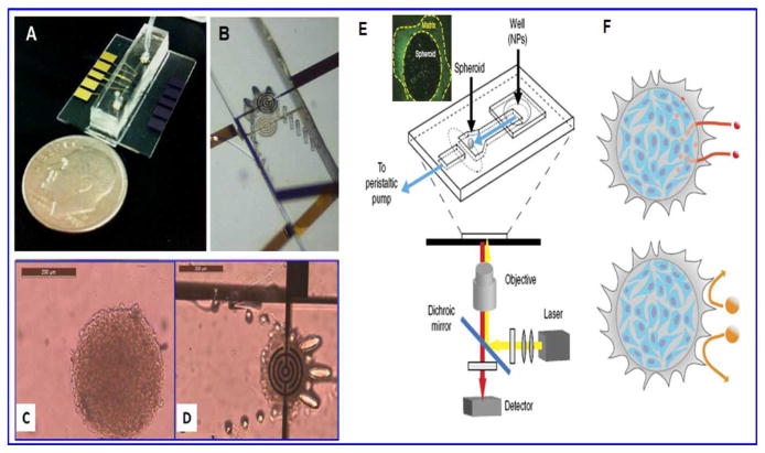
Figure 8.
A) is a microfluidic chip for spheroid capture and real-time impedimetric detection. B) is zoomed area of the microfluidic channel and the trap mechanism for spheroid. C) is the image of a multicellular spheroid before perfusion and D) is the entrapment of spheroid between two impedimetric electrodes. E) Another tumor on chip platform placed on an inverted microscope, the highlighted part is live spheroid and F) is schematic representation showing accumulation of smaller NPs (40 nm) in interstitial tissue whereas escape of bigger NPs from penetration in spheroid matrix. Images A–D are reused with permission from 86 and E–F from 90.

