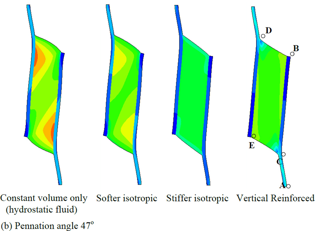
Fig. 4.
Principal strain contours for maximally activated models with different passive material properties. Principal strain is the strain in the maximum principal direction at each point in the image. Pennation angles of 25° (top row) and 47° (bottom row) are illustrated. The initial muscle length corresponded to the length at which the passive materials were in their neutral position and therefore exerted no force before muscle activation deformed them (blue diagram, bottom right illustrates the undeformed 47° pennation angle model). The first column shows the hydrostatic model. The second and third columns show the softer and stiffer isotropic elastic matrix models respectively. The fourth column shows the vertically reinforced model.


