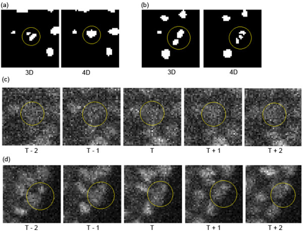
Figure 8.

Examples of different segmentations between methods with 3D and 4D DoG filters. The yellow circles represent nuclear regions. (a, b) Segmentation results of the same regions by the 3D-Dst (left) and 4D-Dst (right) methods. (c, d) Time course of the original intensity images of (a) and (b), respectively. Images denoted 'T’ in (c) and (d) correspond to the images of (a) and (b), respectively. Images at the previous two (T - 1 and T - 2) and next two (T + 1 and T + 2) time points are also shown.
