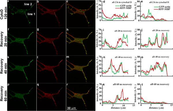
Figure 6.

Live-cell images of another N19-OLG treated with CytD for 2 hours (a-e), after 20 min recovery (f-j), after 40 min recovery (k-o), and after 60 min recovery (p-t). Panels a, f, k, and p show GFP-actin signal; panels b, g, l, and q show RFP-MBP signal; panels c, h, m, and r show the merge of GFP-actin and MBP-RFP signals; panels d, i, n, and s correspond to intensity plots along line 1, and panels e, j, o, and t represent intensity plots along line 2 for GFP-actin (green) and RFP-MBP (red). The intensity plots are in arbitrary units and do not quantitatively reflect the MBP and actin enrichment at the sites analyzed, but show changes in relative intensity of MBP and actin, their location and their degree of co-localization with time. The arrowheads in white indicate regions where ruffles were observed after removing CytD. Scale bar represents 30 μm.
