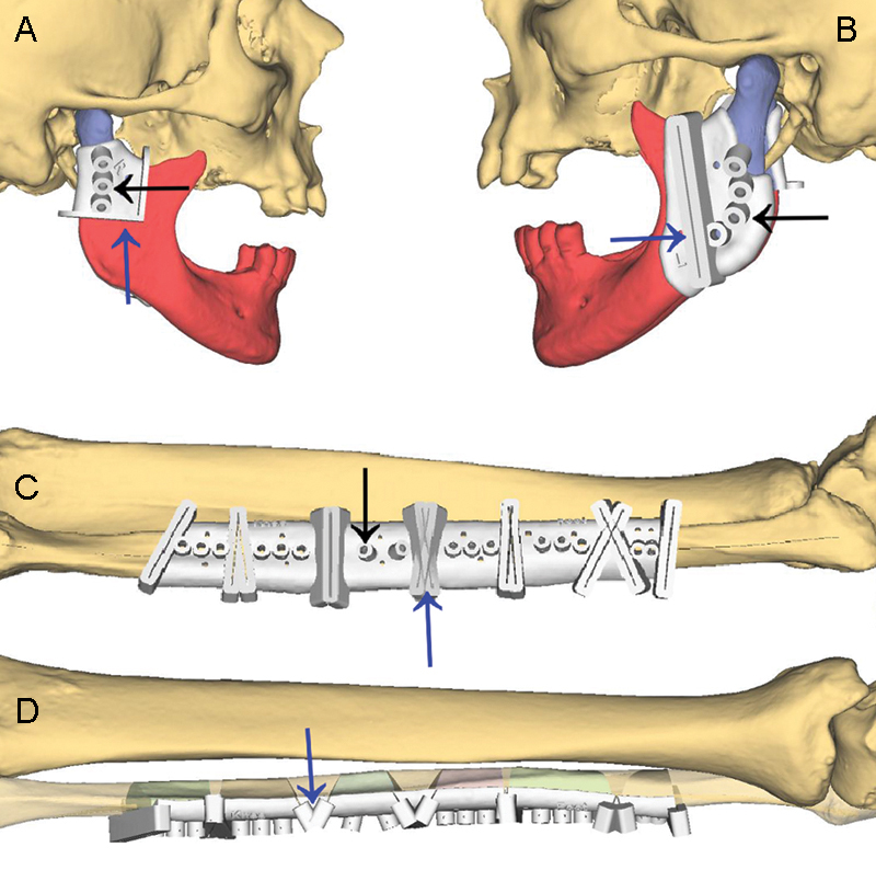
Figure 6.

Computer-aided design (CAD) of resection guides for mandibular resection (A and B) and cutting guides for harvesting fibula segments (C and D). Black arrows indicate drill sleeves that were integrated into the guides and identified the screw holes that were used for fixing the plate to the residual mandible and for fixing the fibula segments to the plate. Blue arrows indicate slots and flanges that help surgeons guide an osteotomy saw.
