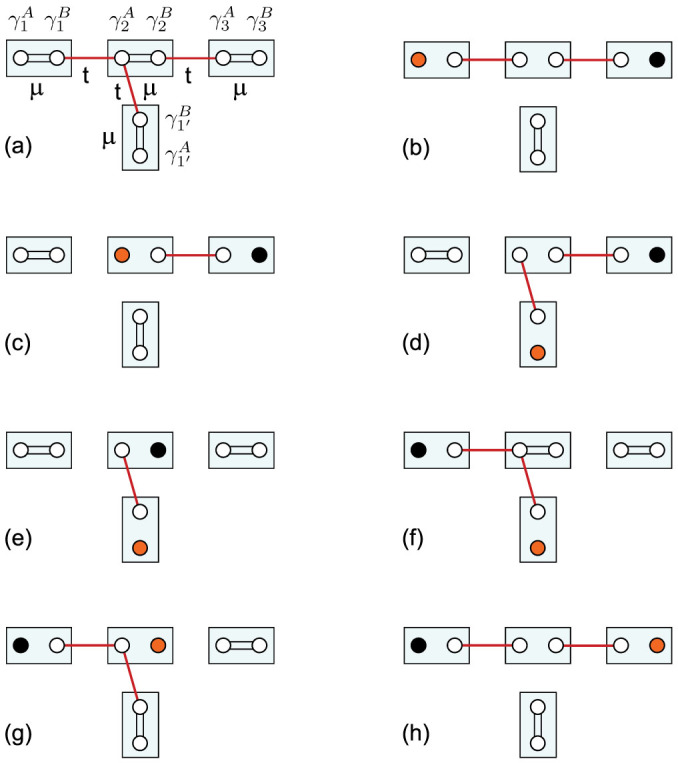
Figure 3. Braiding two unpaired Majorana fermions.

(a) T-junction formed by qubits 1, 2, 3 and 1′, where each qubit is denoted by a rectangular box. Two Majoranas related to the same qubit (e.g.,  and
and  ) can be paired by the parameter μ while two Majoranas related to adjoining qubits (e.g.,
  and
and  ) can be paired by t. (b) Unpaired-Majorana region for the whole horizontal array, where an unpaired Majorana (denoted by a solid circle) is located at each end. (c) Adiabatically tuning μ to nonzero for qubit 1 and turning off t between qubits 1 and 2 drive the left-end Majorana mode (shown in orange) to the middle qubit. (d) Adiabatically tuning μ to zero for qubit 1′ and turning on t between qubits 2 and 1′ drive the original left-end Majorana to the bottom of the T-junction. (e) The right-end Majorana (in black) is driven to the middle qubit by adiabatically tuning μ to nonzero for qubit 3 and turning off t between qubits 2 and 3. (f) The original right-end Majorana is finally driven to the left end by adiabatically tuning μ to a sufficiently large value for qubit 2, tuning μ to zero for qubit 1 and turning on t between qubits 1 and 2. (g) The Majorana at the bottom is driven to the middle qubit by adiabatically tuning μ to zero for qubit 2 and tuning μ to a sufficiently large value for qubit 1′. (h) Adiabatically turning off t between qubits 2 and 1′, tuning μ to zero for qubit 3, and turning on t between qubits 2 and 3 finally drive the original left-end Majorana to the right end. This accomplishes the anti-clockwise braiding of two Majorana fermions.
