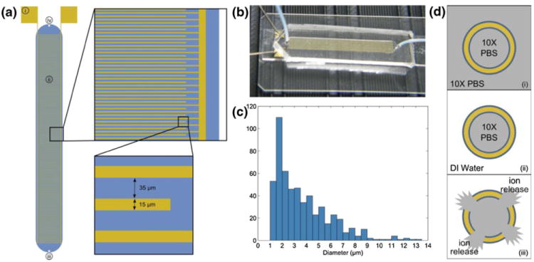
Fig. 1.

(a) Schematic of interdigitated electrode impedance sensing device. Each electrode finger is 15 μm wide with a 35 μm gap between electrodes. Labeled components are (i) gold contact pads where micromanipulator probes contact the device, (ii) sensing region/fluidic chamber, (iii) fluidic inlet port, (iv) fluidic outlet port. The blue region represents the fluidic chamber defined by the PDMS cover. (b) Photograph of device with PDMS cover mounted on a microscope slide. Micromanipulator probes can be seen in contact with the device. (c) Histogram of liposome diameters as determined by optical microscopy (mean diameter=3.682 μm, standard deviation=2.262 μm) and analysis with ImageJ software. (d) Illustration of liposome sensing concept: (i) liposomes are hydrated in 10X PBS, producing ion-encapsulating particles, (ii) the external media is replaced with low-conductivity DI water, (iii) ion release is triggered and impedance change is measured in order to quantify liposomes present in the sensing device
