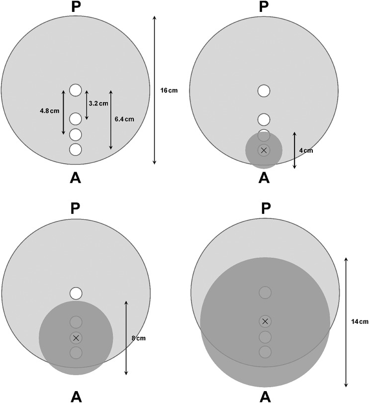
Figure 1.
Schematic representation of SedentexCT DI phantom (top view). White circles correspond to holes available for ion chamber placement. Field of view (FOV) positions for all three FOV sizes are shown as dark grey circles. “×” marks the isocentre of the FOV and the position of the ion chamber. A, anterior; P, posterior.

