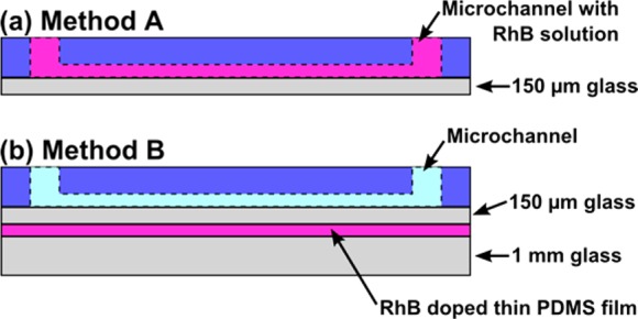
Figure 2.

Schematic representation of two methodologies employed to measure temperature in iDEP microfluidic devices. The 2D schematics correspond to the cross-section view of the iDEP device shown in Figure 1 (not to scale). (a) In method A, the channel (dotted line) is filled with the RhB containing buffer (pink). (b) In method B, a thick and thin glass slide sandwich the RhB doped thin PDMS film located 150 μm below the channel. Channel is filled with the desired working buffer which does not contain RhB (light blue).
