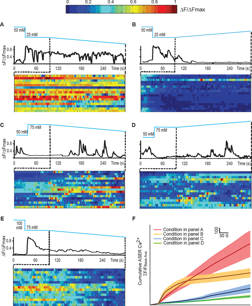
Figure 3. ASER calcium imaging in response to salt gradients delivered by microfluidic device.
(A–E) Sample traces of G-CaMP3 in ASER in one animal and the heat maps of G-CaMP3 in ASER in multiple animals that raised at 50 mM responding to a decreasing gradient of NaCl starting at 25 mM (A), or raised at 50 mM responding to an increasing salt gradient starting at 25 mM NaCl (B), or raised at 50 mM responding to a decreasing salt gradient starting at 75mM NaCl (C), or raised at 50mM responding to an increasing salt gradient starting at 75mM NaCl (D), or raised at 100 mM NaCl responding to a decreasing salt gradient starting at 75mM NaCl (E). To calculate ΔF/ΔFmax (A–E), we subtracted the calcium intensity of each time point (F) by the minimal calcium intensity of the time series (Fmin) and divided the difference by the difference between the maximal (Fmax) and minimal (Fmin) calcium intensity of the time series (ΔF/ΔFmax= (F-Fmin)/(Fmax-Fmin)).
(F) Cumulative GCaMP3 signal in ASER neurons as shown in A–D. Solid lines and shadings are mean ± SEM. N>15 animals under each condition. To calculate the cumulative calcium intensity for each time point, we divided the sum of the calcium intensity from time zero to the current time point by the average calcium intensity during the baseline period (i.e. the first 30 seconds).

