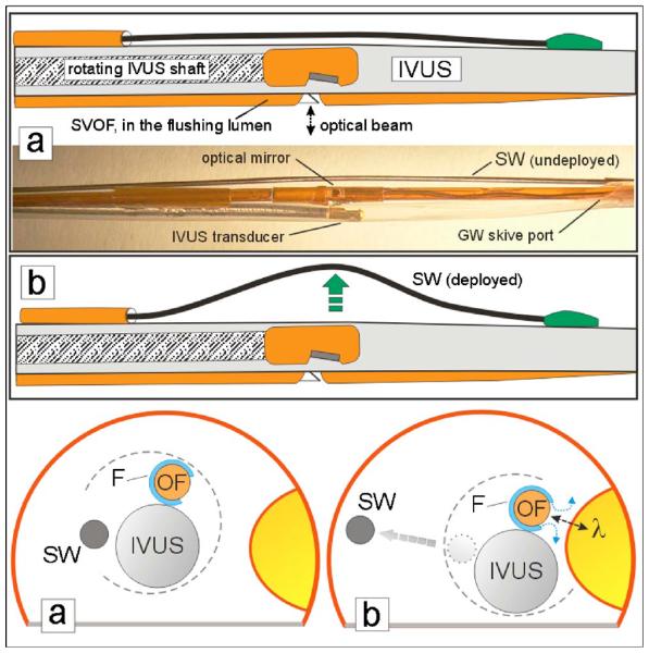
Fig. 2.
Schematic and picture of the three-component construction of the MMC with deployment of lateral (steering) movement with the steering wire (SW). The normally compact MMC components are separated in the photo for clearer viewing. The SW in the undeployed state (a) is near the IVUS sheath and is mounted so that deployment (b) by pushing on the wire will move the MMC close to the fluorophore target in the phantom artery wall.

