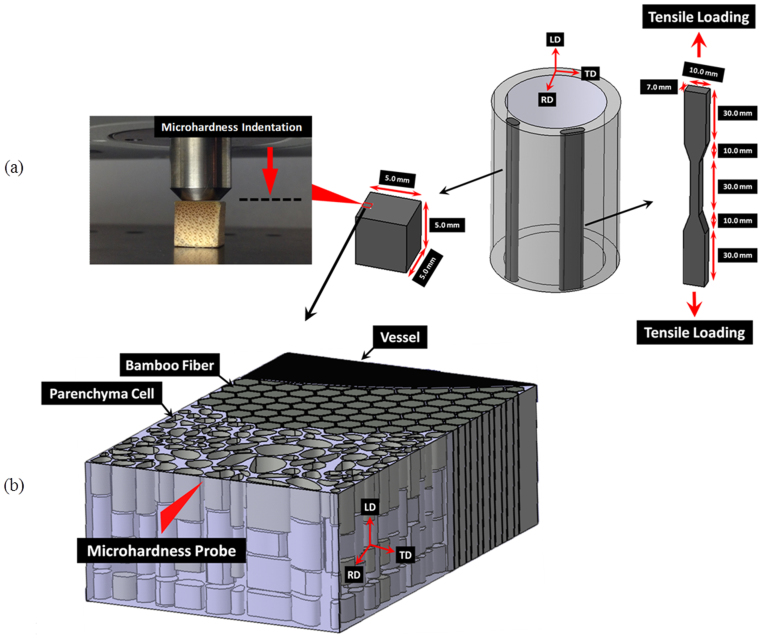
Figure 2. Samples and experimental configuration.
(a) microhardness (left, cubic) and tensile (right, dog-bone shaped) testing samples, along with the microhardness indentation configuration; (b) schematic representation of microhardness probe loading direction (the red arrow) with respect to a vascular bundle.

